What Type of Printing Issue Are You Experiencing?
What is the issue related to?
Using incorrect film, ink and queue combinations will create inconsistent results.
Try printing with the image meeting the requirements.
1. Perform Step Adjustment
2. Perform Head Space Adjustments
3. Perform Color Adjustments
4. Perform Bi-Directional Adjustments
If your issue was not listed or was not resolved, please click on the link to create a support ticket. Be sure to include any troubleshooting steps you took in order for us to assist you efficiently.
If you already have a ticket, there is no need to create a new one, simply respond to your previous ticket. If your issue has been resolved by using the troubleshooting guide, please update your ticket with this information.
For Warranty Parts, an invoice will be supplied for shipping of the parts and a return label for the part(s) needing replaced will be provided. In your ticket, be sure to include:
Ship To Address:
UPS Shipping Method
Printer or Dryer Serial Number
We also value your feedback when using this troubleshooting guide. We want to continue improving this system, so please feel free to leave any comments or suggestions in your ticket. Let us know if this was able to resolve your issue or not.
When the print is coming out of the printer, is the alignment issue Left and Right or Top and Bottom?
Left and Right Alignment Issue

Top and Bottom Alignment Issue

Top and bottom registration issues are associated with stepping. Check each of the Step Offset values in Print Exp. For any Pass Mode setting that is something other than 0, change it to 0, choose save and check the next Pass Mode. As long as all Pass Modes are 0, it does not matter which selection you have when exiting this window
1 Pass
2 Pass
3 Pass
4 Pass
5 Pass
6 Pass
8 Pass
10 Pass
12 Pass
16 Pass
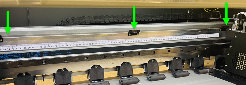
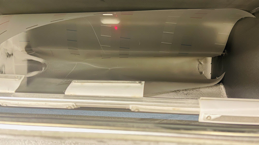
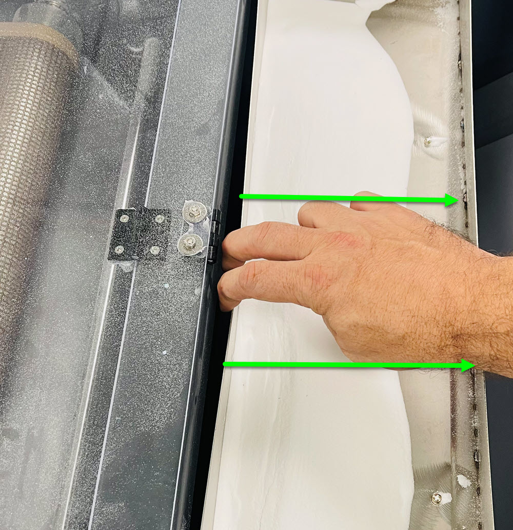
Loosen the film roll on the back of the printer using the left and right tension knobs in order to stop the film from slipping as it steps. When the film is pushed away from you and into the printer, it should unroll for 3-4 seconds on its own.
In PrintExp:
1. Perform Base Step Adjustment
2. Perform Vertical Offset Adjustment
Left and Right alignment is typically from not aligning the horizontal head space properly. This is usually after removing and installing a print head.
Once this is corrected, perform a bidirectional adjustment.
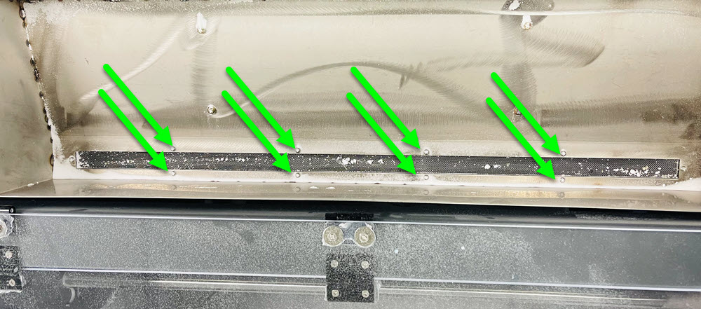
The encoder strip runs along the back side of the head carriage, if it is scratched or damaged, replace it. If it is not damaged but dirty, you can clean it with isopropyl alcohol and a lint free cloth.
Click on the Image to Enlarge in a New Window
If your printer is still within the 1 year warranty period, open a ticket and someone will assist. If it is out of warranty, click the link to purchase.
Blurry prints are caused from alignment issues specifically with color and bidirectional adjustments.
When color adjustments are made, every channel is aligned to the first channel on the first head. If the channels are out of alignment, the ending result can be blurry or grainy prints. Perform both sets of adjustments to correct the issue.
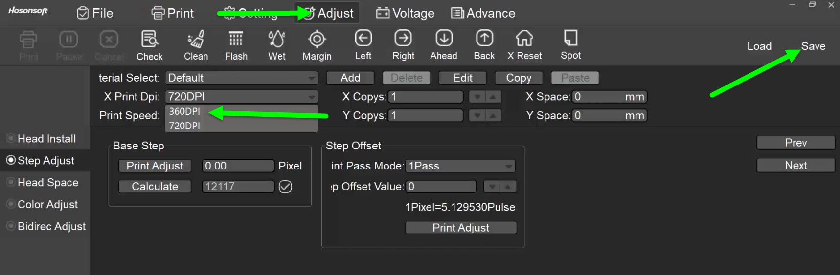
Is your print Blurry or Distorted? Here is an example of distorted print

Most of the time, distorted prints are from an improper setting in PrintExp. If the resolution is set to 720, change it to 360 and select Save.
Click on the Image to Enlarge
The first step to determine why there are lines in the printed image is to always print a nozzle test. After printing, what does the nozzle test look like?
Loosen the film roll on the back of the printer using the left and right tension knobs in order to stop the film from slipping as it steps. When the film is pushed away from you and into the printer, it should unroll for 3-4 seconds on its own.
Click on the downloadable file and follow the instructional video on how to calibrate the Y stepping motor.
Click Here to Download the Metric Ruler
If a print head was installed crooked, this can create registration issues. Follow the instructional video on how to test and correct a print head when crooked.
After the Y Motor calibration, perform a base step and vertical offset adjustment.
1.Open PrintEXP and Perform Base Step Adjustment
2. Perform Vertical Head Space Adjustment
Check each of the Step Offset values in Print Exp. For any Pass Mode setting that is something other than 0, change it to 0, choose save and check the next Pass Mode. As long as all Pass Modes are 0, it does not matter which selection you have when exiting this window
1 Pass
2 Pass
3 Pass
4 Pass
5 Pass
6 Pass
8 Pass
10 Pass
12 Pass
16 Pass
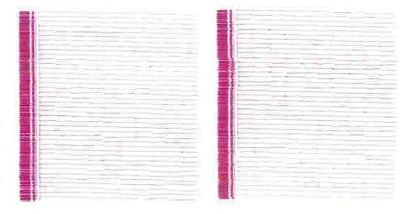
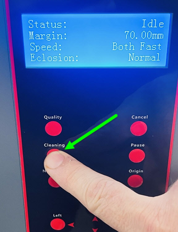
We need to determine if it is air in the print head or if the nozzles are clogged.
Perform a nozzle test, press the cleaning button on the control panel of the printer and then perform another nozzle test. Compare the nozzle tests.
If the nozzles that were dropped out are now printing or the dropped nozzles are printing and now others are not printing, this could be from air or foam in the print head.
If the same nozzles are dropped out and not printing, this may be a head clog.
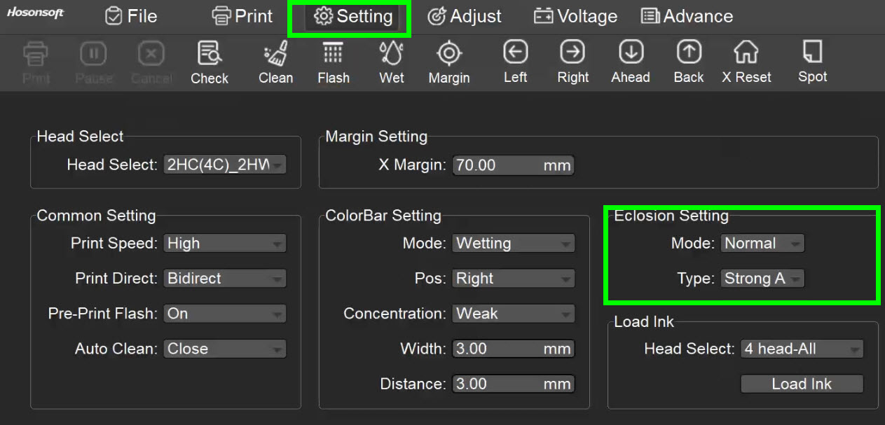
The Eclosion setting is a feature in which it changes the way the print head overlaps while printing. The minimum Eclosion setting we recommend is Normal. The Type for the DTF24H2 is recommended at Strong A, but Fog Type can still yield a smooth print. The lower the setting, the faster it will print but the more evident banding can become. The higher the setting, the slower it will print but the less evident banding can become.
Using Custom can achieve great results without the need to slow the printer down drastically. Normal Eclosion would be equivalent to 60% custom, whereas Super Eclosion is 100%. Using Custom at 80%, or similar, is a good trade off between slower speeds and smoother graphics.
Click on the Image to Enlarge in a New Window
Since the nozzles are now printing, it may have been air in the system. As you continue to print, if there appears to be lines in your print, cancel the job and perform another nozzle test.
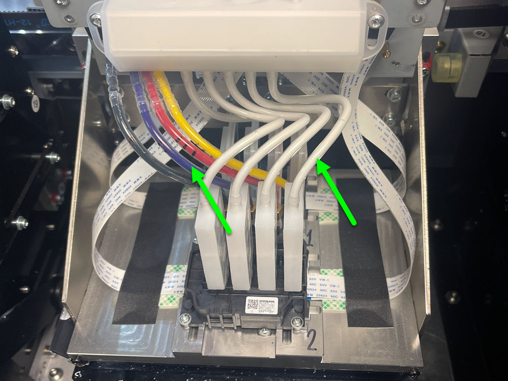
When nozzles move around and/or drop out and come back, air is entering the system at some location. This is usually at the damper level. If this is white ink, use the following video to determine which damper could be causing the issue.
Access the print head area and press down on all dampers, ensuring they are even with each other and not rocked forward or backward.
Each group of nozzles in the nozzle test pattern is called a Channel. A white print head has 8 channels of white, whereas a color head has 2 channels of each color. In the nozzle test, are the color or the white channels effected? If both, choose White Ink as your option and after the white ink questions, the remaining information applies to all.
Example of a Single Black Channel
It is possible there is build up in the print head spike plate. There are two effective methods to cleaning the spike plate, manually flushing the print head or using an ultrasonic cleaner. If you do not have an ultrasonic cleaner, you can attempt to flush the head manually, but depending on the severity of the nozze test, the ultrasonic cleaner may be the better option.
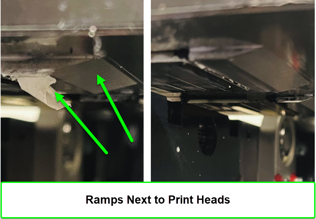
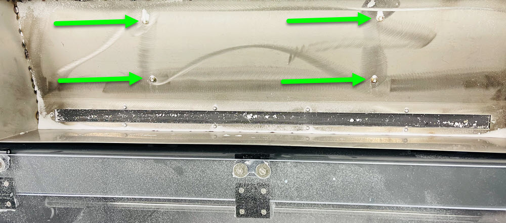
Make sure the wiper blade is straight and not warped. If it is warped, straighten it out. You can loosen the side screw to adjust the blade, but be sure not to adjust the height of the blade to ensure it is wiping the head properly. Clean the wiper blade, cap tops and the bottom of the head carriage, specifically the ramps on both the left and right side of the heads. Clean the ramps with a dry cloth, attempt to avoid touching the surface of the print heads.
Click on the Images to Enlarge in a New Window

To access and clean the print head ramps, remove the wiper blade assembly from the cap plate.
Using an ultrasonic cleaner can be quick and effective. Follow the video showing how to protect the head and use the cleaner.
In the first video, follow along until 10:05 and then follow the second video.
If none of these resolved the issue, you may qualify for a print head replacement:
The DTF24H2 print head warranty includes the replacement of up to 2 print heads within the first 6 months of when the printer has been shipped from our facilities.
You must be using our ink, so please take a photo of the CMYK and White ink bottles you are currently using, including the batch number and fill date on the bottles.
The heads you have now, must also be sent back after installing the new print heads. You are responsible for shipping costs from us to you, but we will provide a return label. If you want a quote on expedited shipping, let us know, otherwise we will invoice you for ground shipping.
Please confirm the correct shipping address to avoid any delays.
If you do not qualify for the warranty, you can Click Here to Purchase Print Head
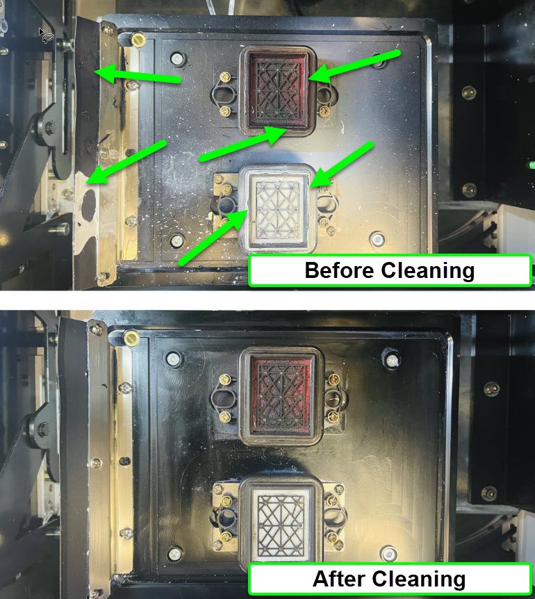
If the issue is with all colors, we need to make sure the cap tops and print heads are aligned properly.
Next, we can determine if the pumps are working properly.
Your printer has a 1 year warranty from the time it shipped from our facilities. If you are out of warranty, you can Click Here to Purchase the Waste Ink Pump
With water based inks, the heads can dry out quicker due to evaporation. We recommend a humidity level of a minimum of 40% but the system performs optimally at 50-60%.
Install an evaporative or cool mist humidifier in the area to increase humidity to a proper level.
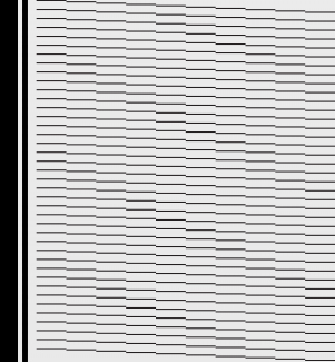
Distorted lines in the nozzle test are typically caused from deflection. This is where the nozzles are not jetting straight down but at an angle. Even if all nozzles are jetting, if they are deflected, this can cause banding issues. One method to correct deflected nozzles is to wet cap the print head.
Example of Deflected Nozzles
Since this is a head clog, the next option would be to wet cap the effected print head(s):
Confirm that no ink lines are pinched shut and check the circulation speed controller in the right side door of the printer. When rotated to the right, check to see if the dial is rotated anywhere from 1/2 to 3/4.
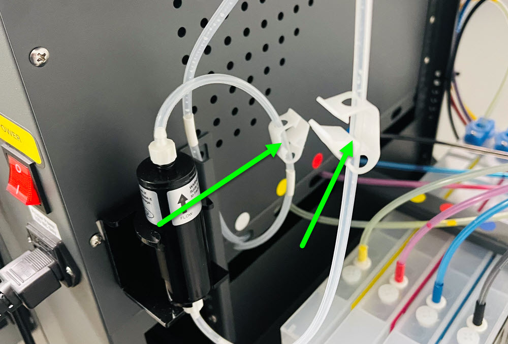
Confirm that the circulation speed controller is set to a minimum of 50% but usually no more than 70%.
The circulation pump may be on a timer. When the circulation is turned on, you can feel the pump and it will vibrate. If the pump is not vibrating, power off the printer and power back on, the pump should turn on within 1-2 minutes. Once the pump is vibrating, remove the lid from the white ink tank. The white ink return line is connected to the top of the tank. Reaching inside of the tank, grab the ink line that is connected to the inside of the tank and gently lift it up to see if ink is flowing.
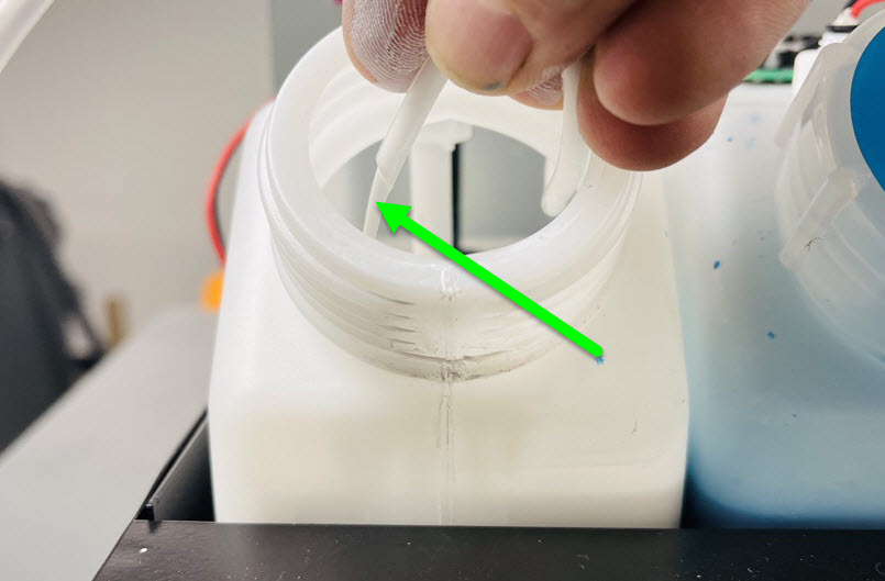
If ink is not circulating, your pump is on and no ink lines are pinched off, the circulation pump needs replaced. Your printer comes with a standard 1 year warranty from the time it ships from our facilities. If you are within warranty, you can create a ticket for assistance. If you are out of warranty, you can purchase the pump here:
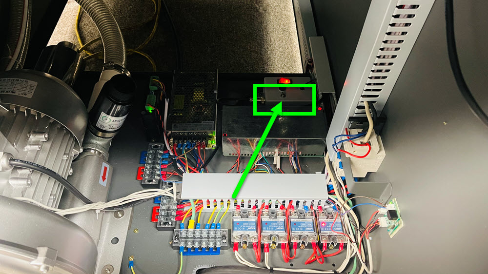
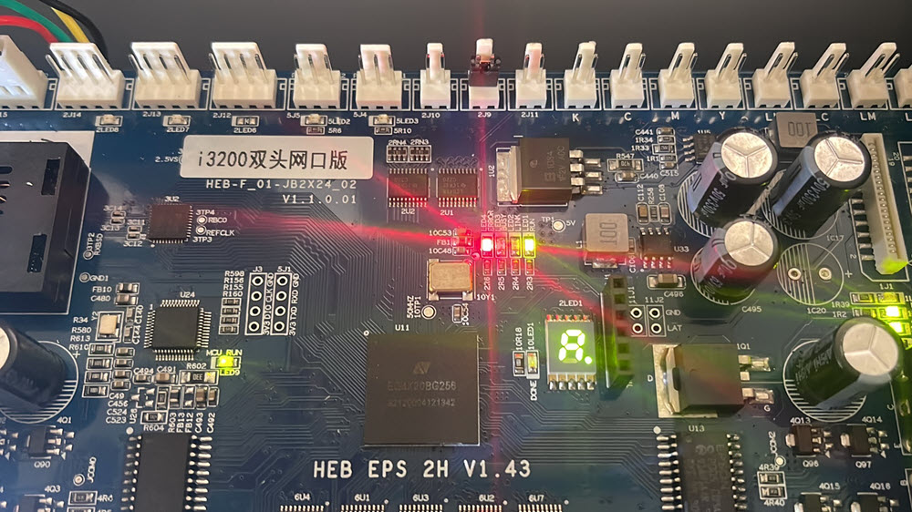
Power cycle the printer. If there is still a red light on the board, follow the video then open a ticket with your results.
If nothing is printing and there is no red light on the head board, perform a load ink on all heads. This is in PrintExp > Settings > Load Ink. After 20 seconds, press stop in PrintExp or Cancel on the printer control panel. Press the left arrow one time to lower the capping station (inkstack) and then press and hold the left arrow to move the head away from the capping station. Is there ink filled up in each of the cap tops?
Press the cleaning button on the printer control panel to remove the ink from the cap tops.
Even though there is no red light, something could still be stopping the printer from printing.
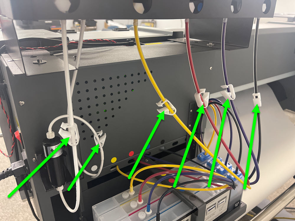
Check to see if there is ink from the tanks to the cartridges and from the cartridges to the dampers.
Click on the Image to Enlarge in a New Window
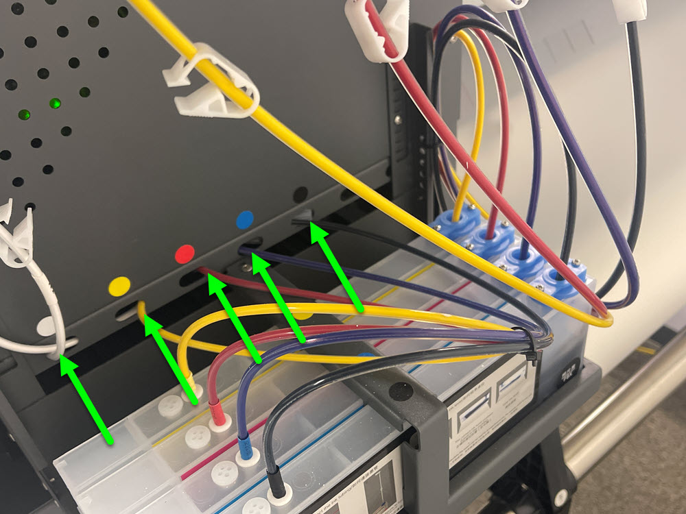
Check to see if the ink lines and waste ink pumps are pinched shut and not allowing ink to flow through the system. If they are, unclip or unpinch them and peform another load ink, head clean and nozzle test.
Perform one or more Load Ink procedures until ink is flowing through the system. Perform a head clean and nozzle test.
Check the breaker in the service panel in the building and confirm there is 208V-240V in the receptacle
If a breaker will not stay in the up position, it would need replaced. Please open a ticket for further assistance.
If the printer powers on but you have another power or part issue, please choose from the following:
The White Ink Stirring Motor is on a timer. Turn the printer off for 10 seconds and then power the printer back on. After the printer iniatizes, wait an additional minute for the stirring motor to turn on.
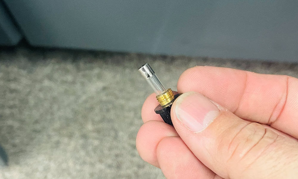
Some stirring motors have an inline 1 amp quick (fast) blow fuse mounted on the back of the unit. Check to see if the fuse is blown by unscrewing the holder and testing for continuity.
The stirring motor is covered under warranty for one year from the time the printer shipped from our facilities. If you are within the warranty period, open a ticket for a replacement motor. If you are out of warranty, Click Here to Purchase the Stirring Motor
The White Ink Circulation Pump is on a timer. Turn the printer off for 10 seconds and then power the printer back on. After the printer initializes, wait an additional minute for the white ink circulation pump to turn on.
The circulation pump is covered under warranty for one year from the time the printer shipped from our facilities. If you are within the warranty period, open a ticket for a replacement pump. If you are out of warranty, Click Here to Purchase the Circulation Pump
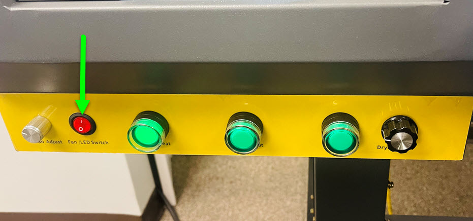
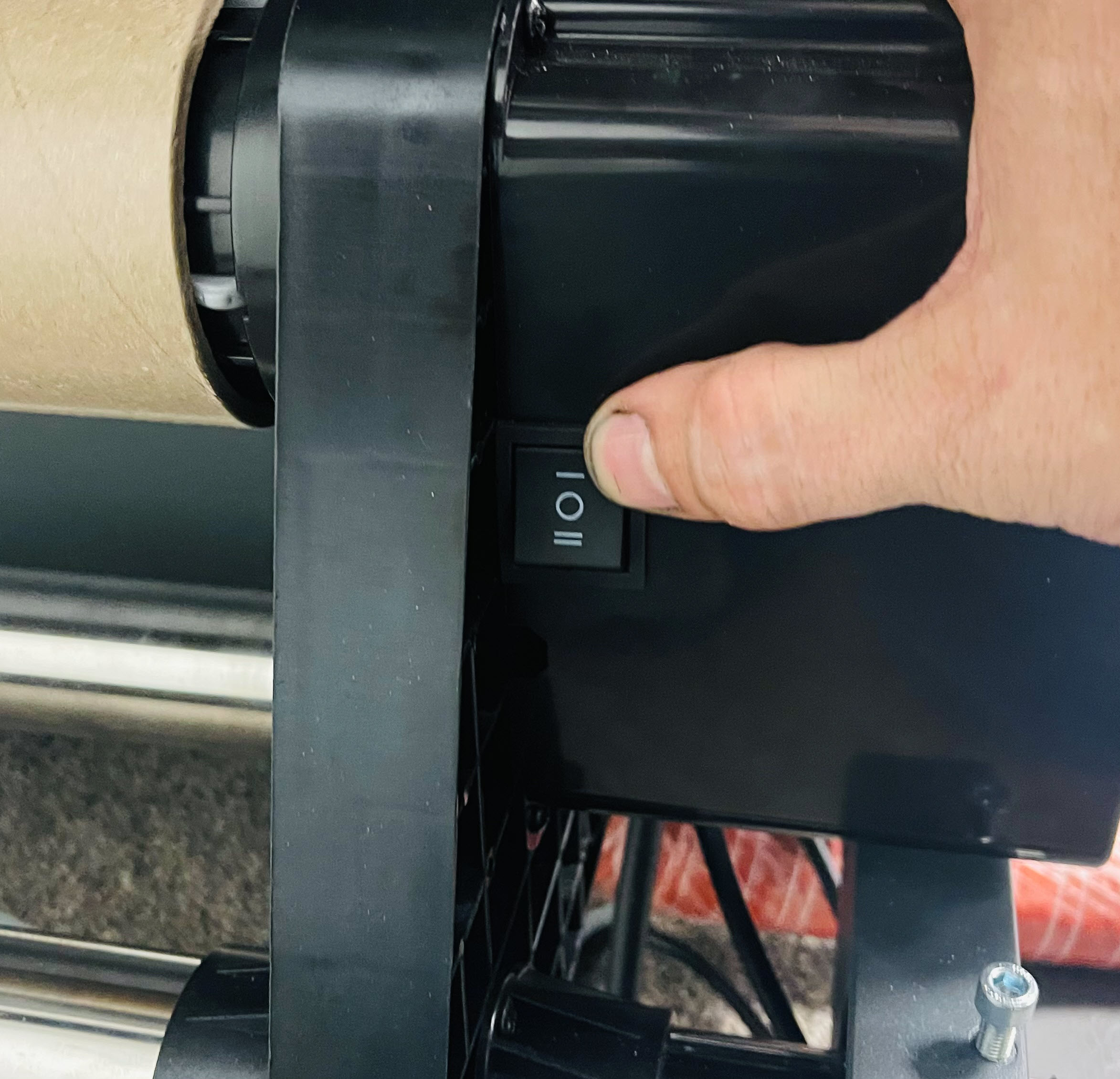
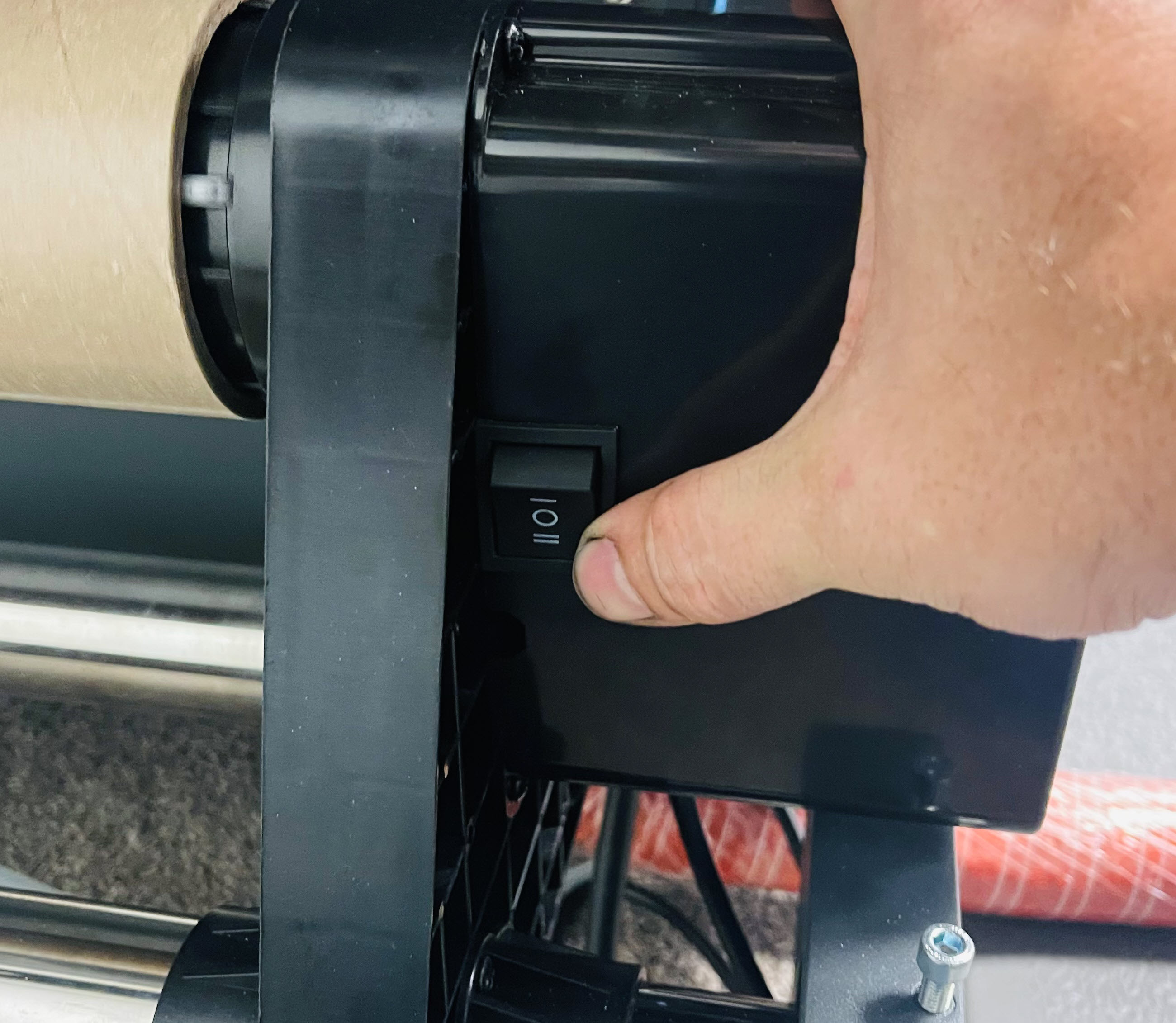
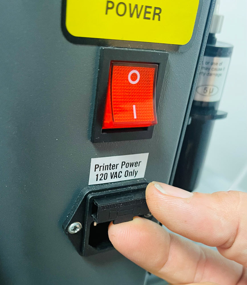
The interior LED power has a shared switch for both the LED and the Film Vacuum Fans, press the button so it is in the 1 position. What is the result?
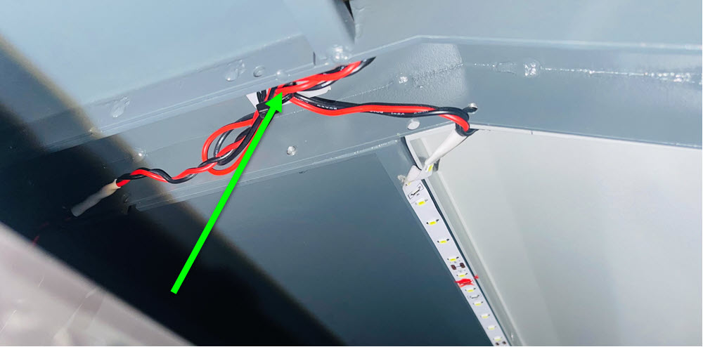
Check the connection of the LED strip to the power cable. If everything looks correct, open a ticket for further assistance.
The capping station pump is covered under warranty for one year from the time the printer shipped from our facilities. If you are within the warranty period, open a ticket for a replacement pump. If you are out of warranty, Click Here to Purchase the Capping Station Pump
Perform a load ink on whichever head you are experiencing the issue with, cancel the process after 30 seconds. Press the left arrow one time and the capping station will lower. Press and hold the left arrow to move the head carriage away from the capping station. Observe if the cap top is filled with ink. Press enter to recap the print head. If there was ink in the cap top, press the clean button to remove it.
Since the cap tops are filled with liquid, the pumps appear to be functioning correctly.
Press the left arrow one time and the capping station will lower. Press and hold the left arrow to move the head carriage away from the capping station. Fill the cap top(s) with distilled water or DTF Head Cleaner, then press the clean button on the printer control panel. After the cleaning process is completed, is the cap top(s) filled with liquid?
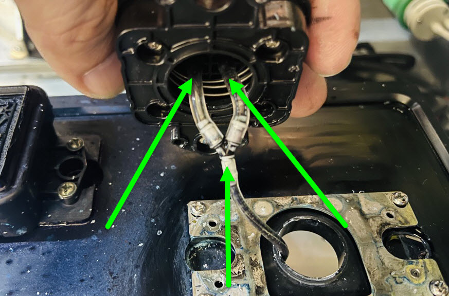
Remove the cap top and check two ink lines connected to the bottom of the cap top to ensure the tubing is connected securely.
Perform a head clean to remove the ink in the cap top. Everything appears to be functioning correctly.
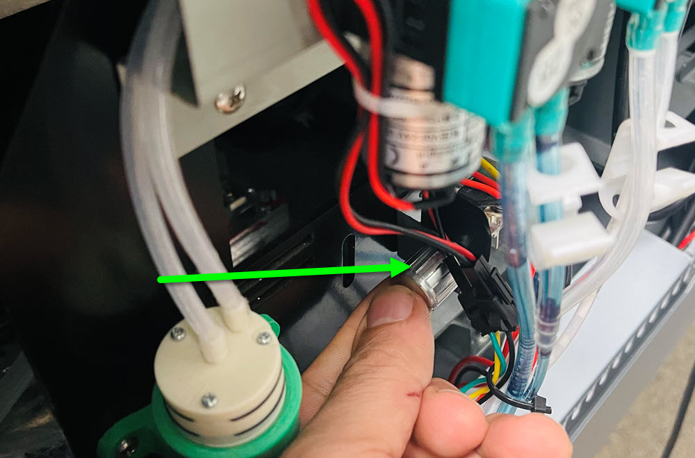
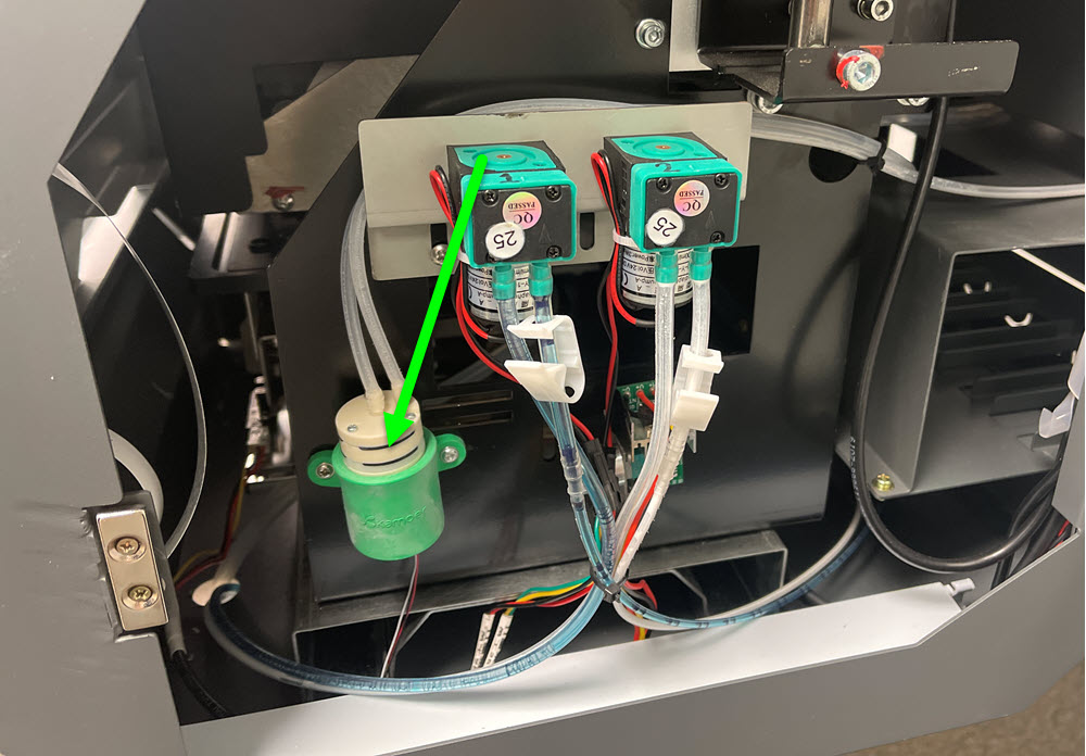
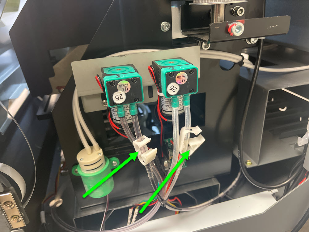
Open the right side door and check the electrical connections at the pump for the head being effected.
Click on the Image to Enlarge in a New Window
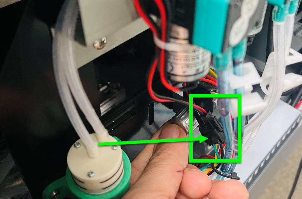
If the connection is good, try disconnecting the pump and connecting it to the other pump power cable. For example, if Pump 1 is not coming on, plug Pump 1 into the Pump 2 power cable and then try loading ink on Pump 2.
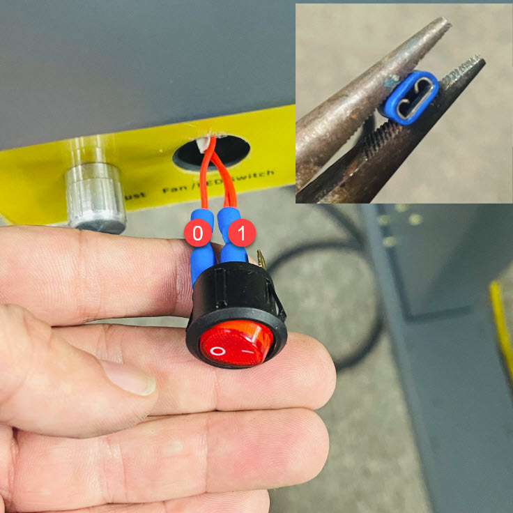
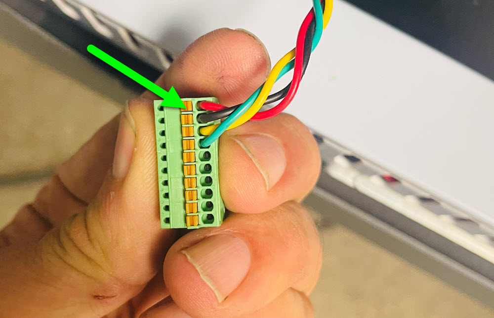
If the connection to the switch is loose, it could cause the switch to not function.
Remove the 6 screws on the cover to gain access to the fan switch.
Press in the clips on the side of the switch and pull it through the front of the printer.
Note the position of each of the wire connections to the switch, the single wire will be in the 0 position of the switch and the two wires will be in the center. Remove one wire and using pliers, gently squeeze the connection for a tighter fit. Do this for both connections, reconnect and test.
What specifically is the issue?
If the heat is working on the printing deck but the buttons are not lighting up, it may be a bad connection to the buttons themselves. Open a ticket for further assistance.
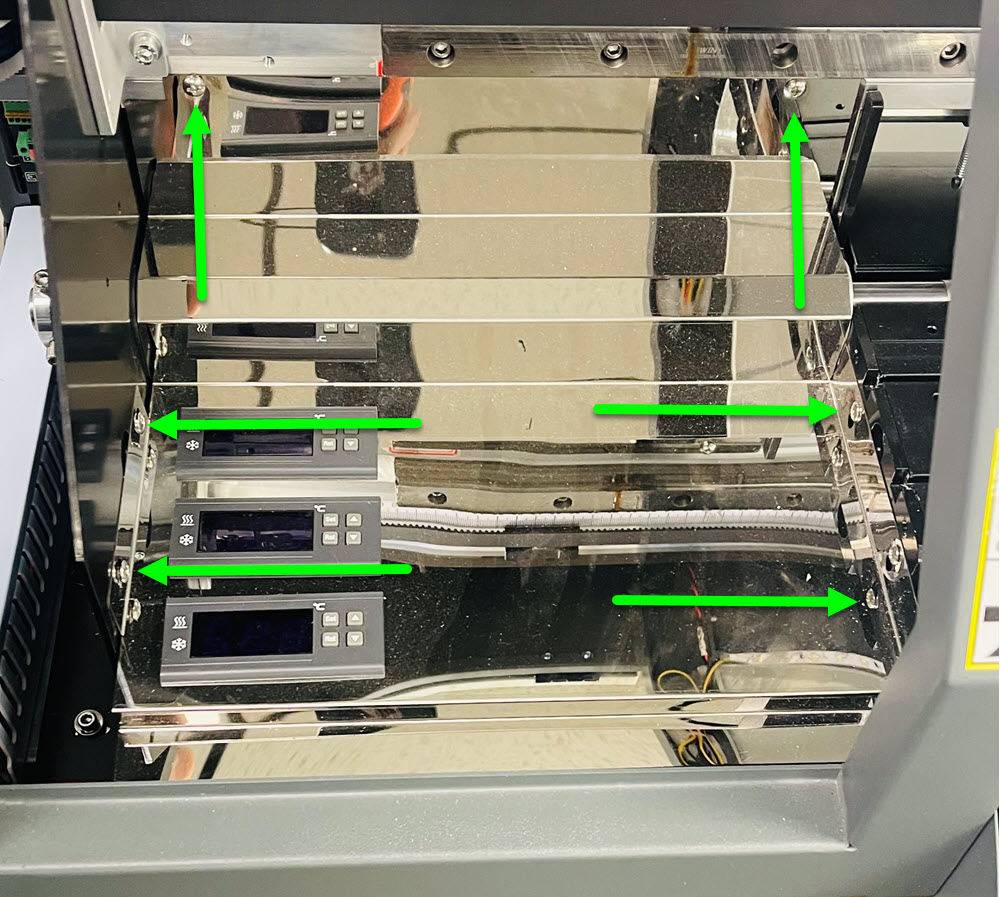
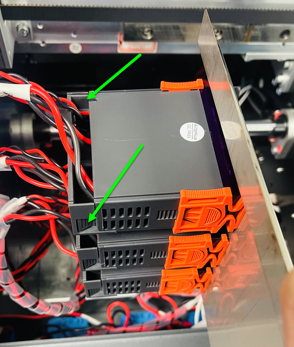
If the heat is not turning on but the buttons are working, there may be a problem with the heating elements or the heat controller. Test another heat zone, if it works, check the connection to the heat controller that is not. Power off the printer and remove the 6 screws on the cover to gain access to the heat controllers.
Squeeze the gray side buttons on the backside of the heat controller and remove it.
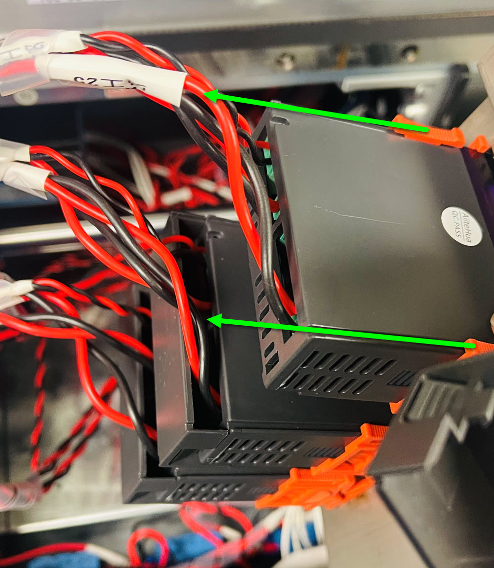
Next, press the side of the orange clip and slide it off of the controller. You may need to press firmly to fully remove it.
Pull the heat controller out of the cover and turn it upside down to gain access to the wire connections. Check the connections and tighten if needed.
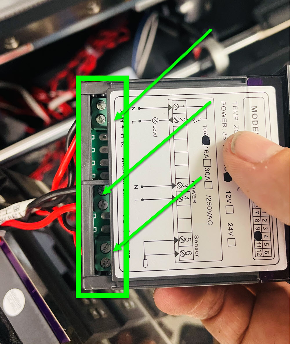
If the controller is bad, you can replace it with a known good one. For further assistance, open a ticket.
What is the issue with the Printer Control Panel?
Open PrintExp and use the buttons on the top of the program. Do the functions work properly?
Click on the Image to Enlarge in a New Window
If ink is throughout the system, ink has filled up in the cap tops and there is no red light on the head board, everything should be functioning properly. If it is not, please open a ticket for further assistance.
If the colors are not correct or missing, the first step is to perform a nozzle test.
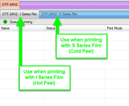
Our inks and films are profiled to achieve as close to color correct prints as possible with a CMYK printer. When the combination of film and inks are not what is recommended, you will not have a desired result for final output. In order to correct this, it is imperative to use ColDesi branded inks and film and printing from the matching Queue, i.e., I Series Film printing in the I Series Print Queue.
Make sure to print out of the queue that matches your film type
I-Series in the I-Series Q
S-Series in the S-Series Q
It is possible it could be film or profile related. If a film has an improper coating, the ink droplets may not be forming correctly. If this is the situation, changing the film as a test may be a good way to know. If it is profile related, we do consistently work on improving color performance and we may have an updated profile available. With either option, please open a ticket with photos of your prints for us to better understand potentially what is happening.
Which software do you need assistance with?
Please select the issue you are experiencing.
If PrintExp is not in English, this could be from either the application language or the printer language. Follow the video to resolve the issue.
If PrintExp will not open due to any type of error, the computer will need updated with Microsoft C++ Redistributable packages. Follow the video to resolve the issue.
This DTF24H2 is not a network printer. The cable from the printer needs to be directly connected to the computer using either an Ethernet Adapter or a built in Ethernet connection with a speed of 100/1000 (Gigabit Per Second) at minimum. If the connection is 10/100 (Megabit Per Second), PrintExp will not connect.
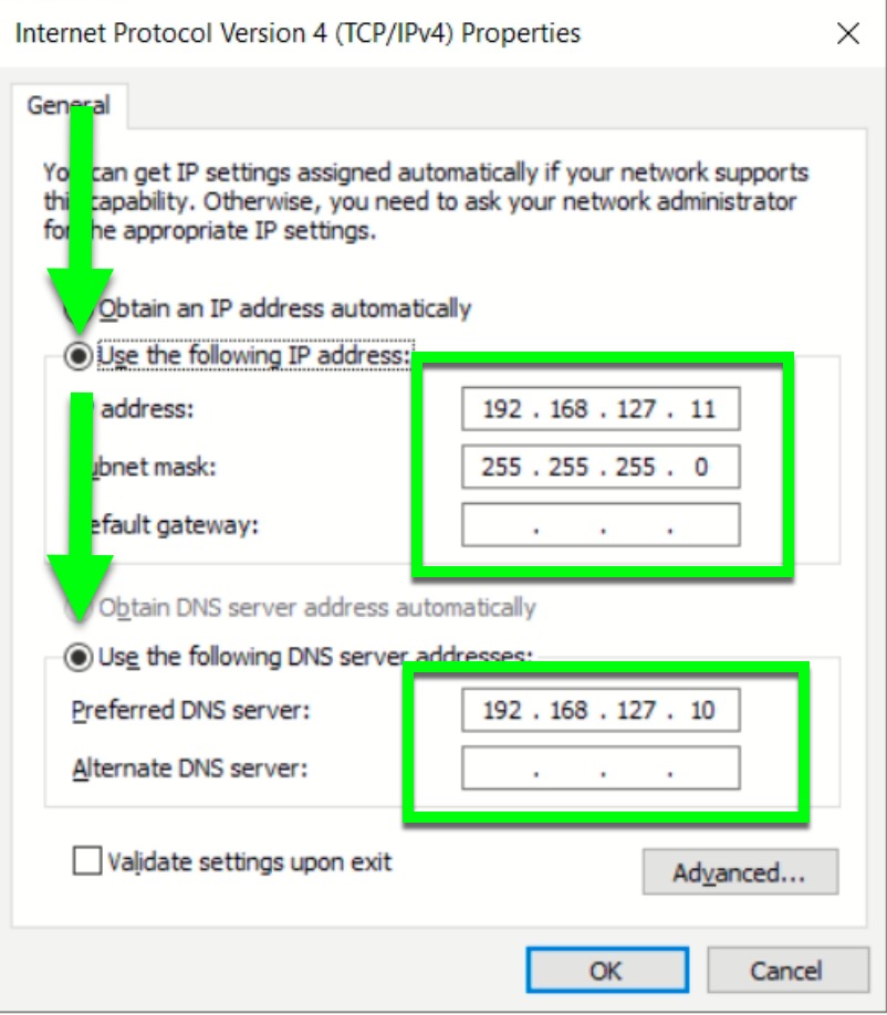
The ethernet address needs to be set for the adapter or built in connection. The printer IP address is static, which means it cannot be changed. This setting is:
192.168.127.10
In order for the computer to read this address, the printer (or non-internet) connection needs to be set to the same domain (192.128.127.xxx) with the last number different than the DTF printer (10).The Printer IP address will be used in the DNS settings. In this instance, we use the following settings to avoid any type of conflict between the computer and printer:
What do you need assistance with?
Your purchase includes an activation code that can be used on a single computer. The software can be operated with a 15 day trial, but if it is not activated prior to the trial expiration, Cadlink will need to reset the trial. Once the activation process has been completed, it is ideal to backup the license file in case the registration for the computer has been removed due to unforseen circumstances. Follow the video to activate the sotware, then back up the license file.
If you did not receive an email with the activation code, please contact your onboarding representative for further assistance. Even though the support department does not have this information, if you would like for us to request this information for you, please open a ticket.
Click on the Image to Enlarge in a New Window
Print Optmizer DTF Edition can be activated on one computer at a time. In order for the software to be used on another computer, the first step would be to Deactivate the product on the licensed computer and then activate on the new computer.
If you have lost your activation code due to a computer crash or some other issue, the activation code needs reset. Please open a ticket requesting the code to be reset. Be sure to include your company contact information along with the activation code and reason for the need for a reset.
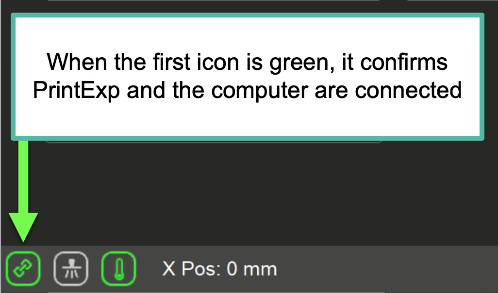
In order for Print Optimizer to release a print job, PrintExp needs to be open and connected to the printer. When attempting to print without PrintExp open, the printer display will have the message OFFLINE.
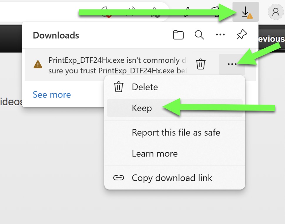
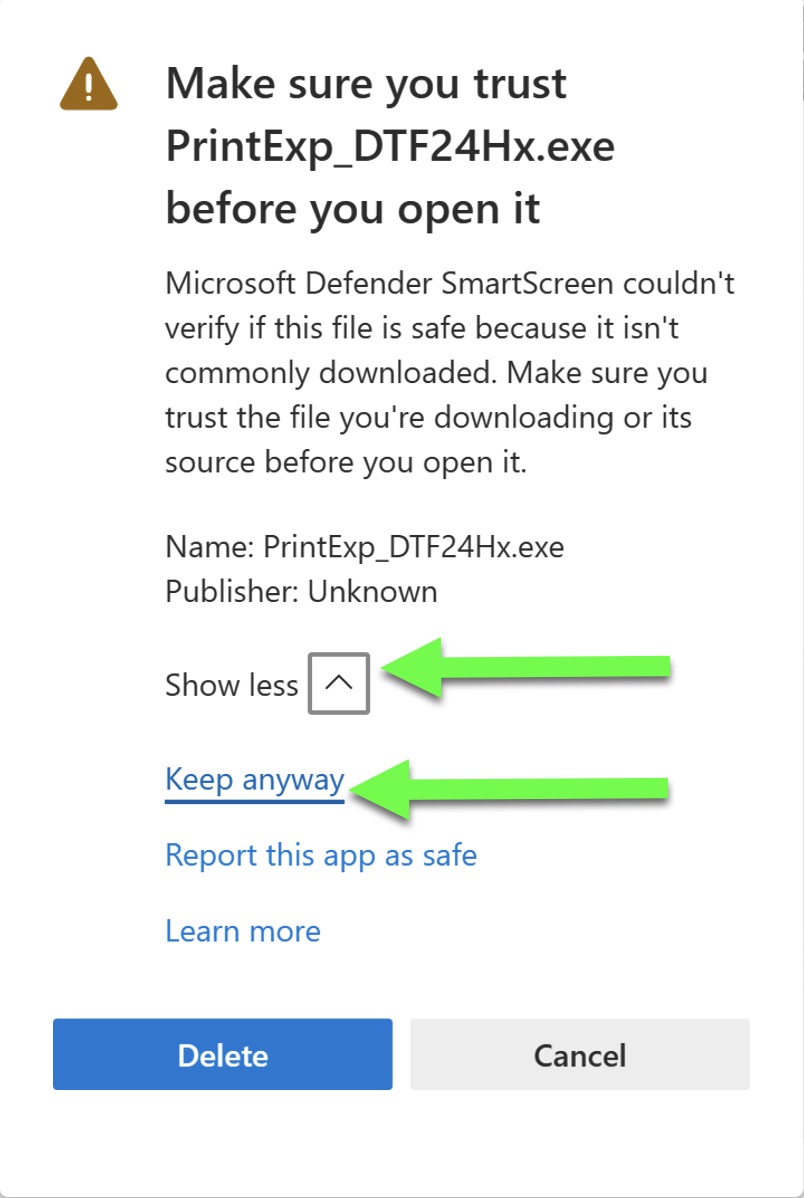
Click Here to Download PrintExp Software
Since this is an executable file, when downloading, please allow your computer to trust the file in order to open it. Follow the videos included here to operate PrintExp software
In this instance, we are using Microsoft Edge as the browser, other browsers should have similar confirmation screens.
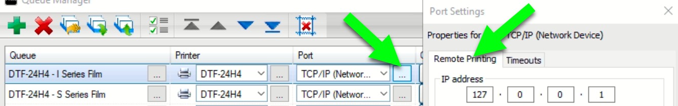
Even though the printer's IP address is 192.168.127.10, when sending a print job from Print Optimizer, we use what is called a loopback IP address, which is 127.0.0.1. In order to utilize this IP address, in Print Optimizer, open Queue > Manage Queues. In the drop down selection in the Port section, choose TCP/IP and under remote printing, change the address to 127.0.0.1 and exit this window. Print Optmizer will not be able to validate this connection, but it is not needed. Once the windows are exited, close the program and open it again in order to lock in the settings.
If your selection in the Port window is already TCP/IP, then choose the ... next to the selection and then choose Remote Printing to access this area
Click on the Image to Enlarge in a New Window
Some computers require the user to be a Local Administrator. If the computer is being operated as a Microsoft Account Administrator, access to release the print job may be denied. Change your account to a Local Administrator.
Some computers may require restarting after changing the account to a local administrator. Restart the computer and try to print the job.
When Print Optimizer will not open, the majority of the time, the issue is related to allowing the 15 day trial to expire. There are several scenarios that could have occurred, if you are presented with a screen showing the trial expiration, copy the contents and include it in a new ticket. Due to the nature of various contributing factors for this issue, open a ticket for further assistance.
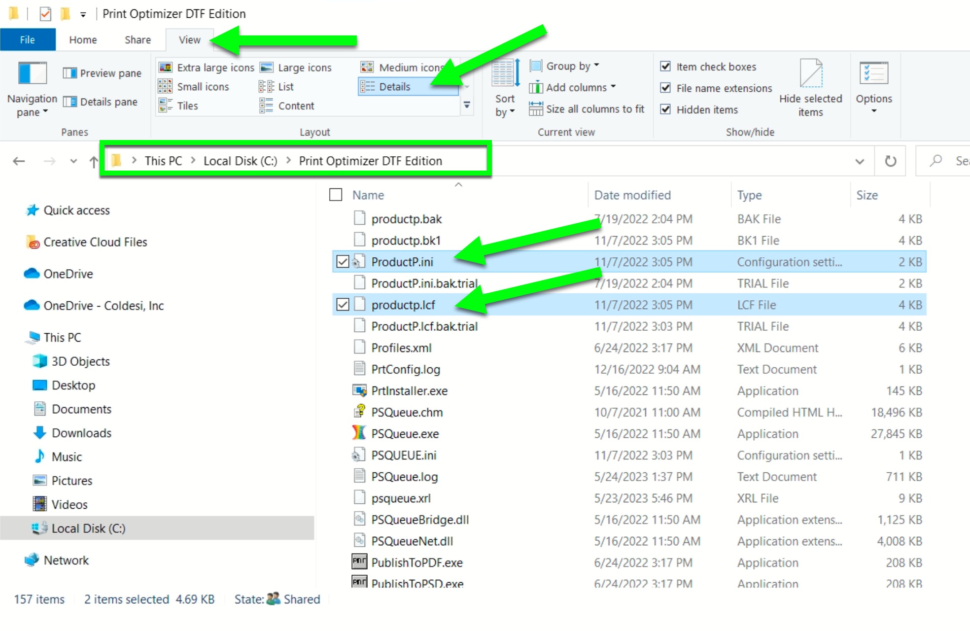
When an image will not import or cannot create a preview, this is due to virus protection software quarantining the CadPDF.exe file in PrintOptimizer. Depending on which virus protection software is being operated, restore the file and exclude the file from future scans. Assuming Print Optmizer is installed in the default location, these are the two files that need to be exluded from the scan:
C:\Print Optimizer DTF Edition\PDF\Bin\CadPDF.exe
C:\Print Optimizer DTF Edition\PDF64\Bin\CadPDF.exe
If you need further assistance, open a ticket.
When colors are innacurate, there are several factors that could be contributing. It is possible we have an updated color profile, but the first thing to always check are the queues, inks, films and nozzle tests. Before requesting any type of color updates to the system (which may or may not be available), follow the troubleshooting steps to ensure something else may or may not be the issue.
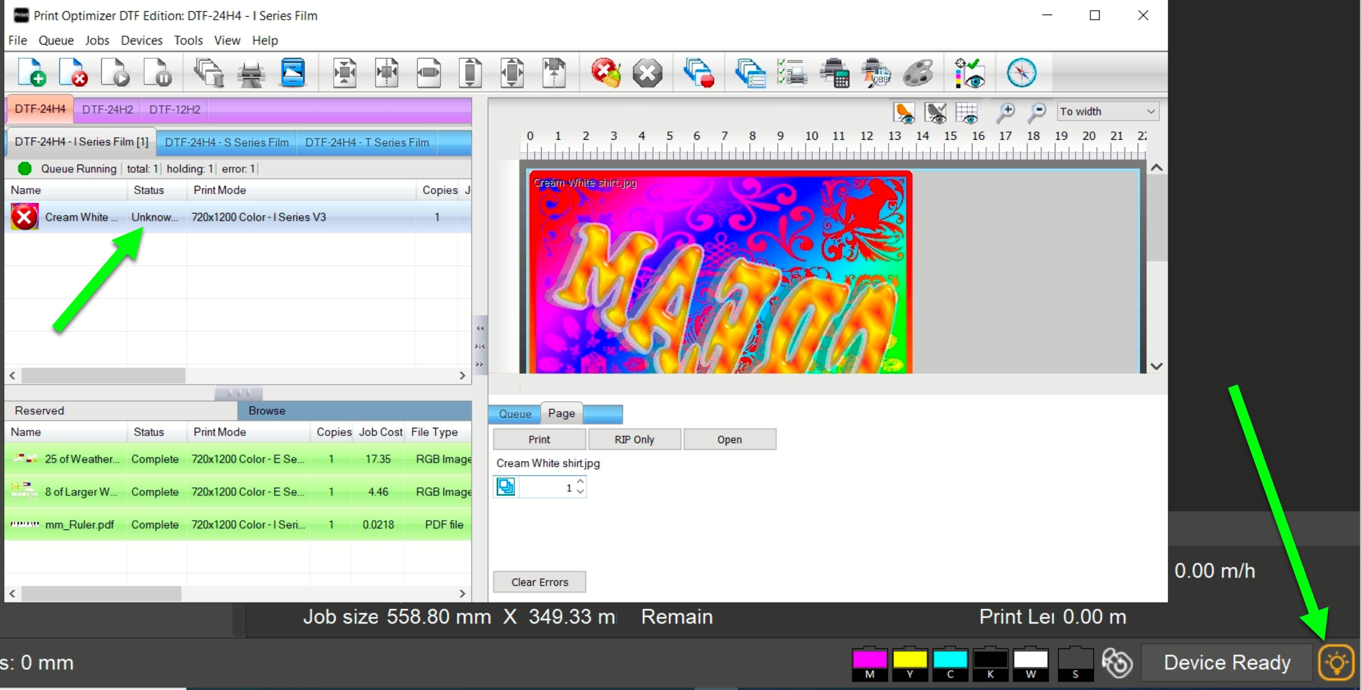
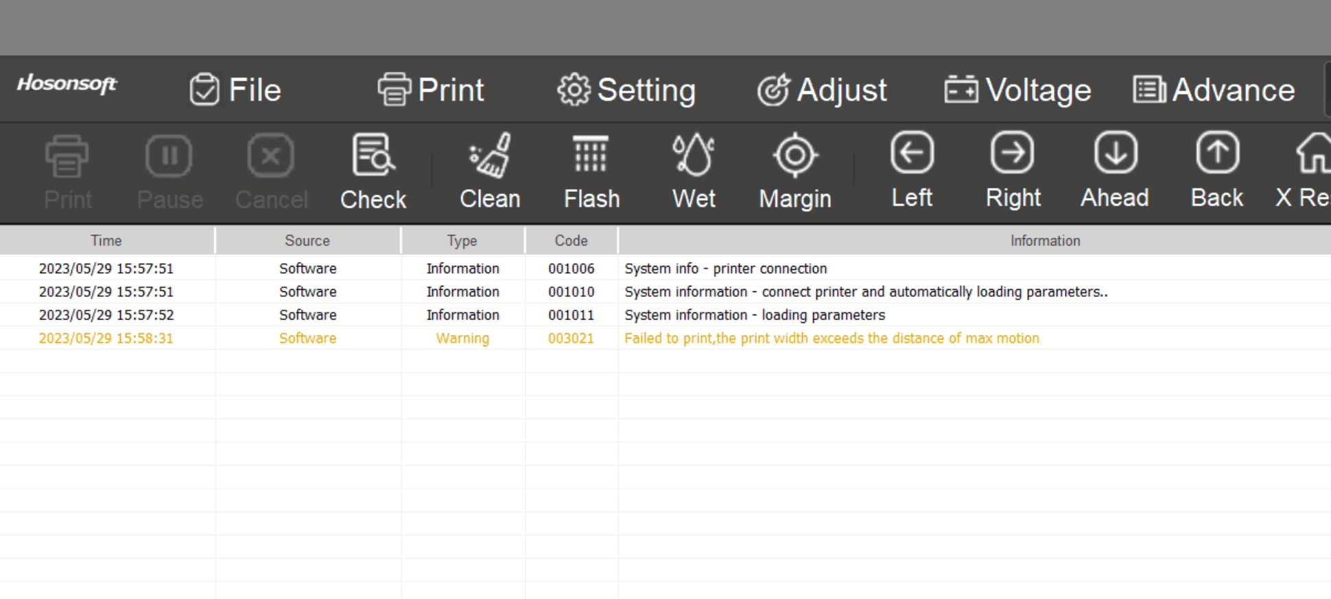
This issue is related to the X Margin or Starting position being too wide for the page size. Follow the video to correct the starting position.
In the bottom right corner of PrintExp, if the icon is orange, click on it and review the log file. If the error is as indicated, choose Continue to correct the issue.
Click on the Image to Enlarge in a New Window
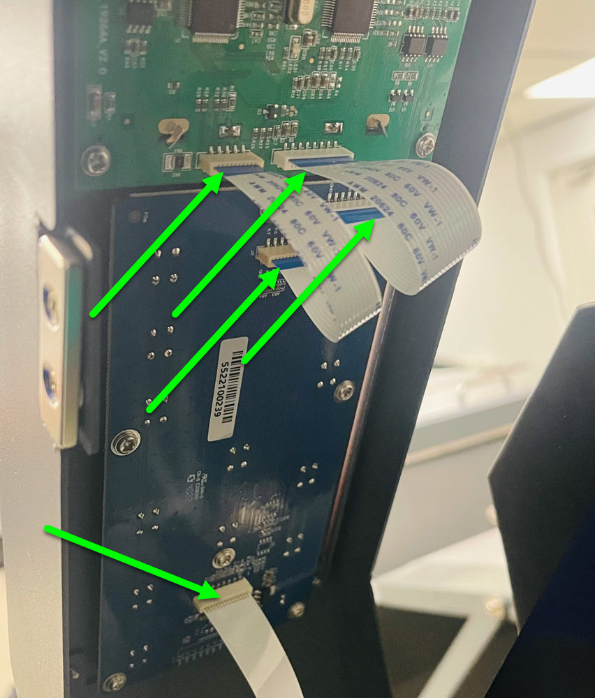
Power off the printer and open the right side door. On the backside of the display and keypad, remove one FFC connection at a time and inspect the pins to ensure there is no damage. Reconnect FFC to the display and keypad. Power on and test.
If the connection appears to be good, the keyboard and/or control panel may need to be replaced.
These parts are covered under warranty for one year from the time the printer shipped from our facilities. Open a ticket for further assistance.
When only the left and right buttons work but not the film advancing buttons, then the issue could be related to a stepping issue.
There may be an issue with the stepper drive, open a ticket for further assistance.
Due to the nature of the issue, open a support ticket for further assistance.
Power off the printer and open the right side door. On the backside of the display and keypad, remove one FFC connection at a time and inspect the pins to ensure there is no damage. Reconnect FFC to the display and keypad. Power on and test.
Test the up, down, left and right buttons on the printer control panel.
When is the OFFLINE message on the printer screen?
Power off the printer and open the right side door. On the backside of the display and keypad, remove one FFC connection at a time and inspect the pins to ensure there is no damage. Reconnect FFC to the display and keypad. Power on and test.
An OFFLINE message could be caused from the fiber optic cables, mainboard, headboard or a bad connection to the keypad. For further assistance, open a ticket.
What is the issue related to?
What issue are you experiencing?
The power cable to the pump may be malfunctioning. Open a ticket with the results of your test.
Open PrintExp and use the buttons on the top of the program. Open a ticket with the results of your test.
Click on the Image to Enlarge in a New Window
Since the buttons are working but the display is not, then the display would need replaced. The DTF printer comes standard with a one year warranty from the time of shipment from our facilities. If you are within the warranty period, please open a ticket for further assistance.
What is the issue related to?
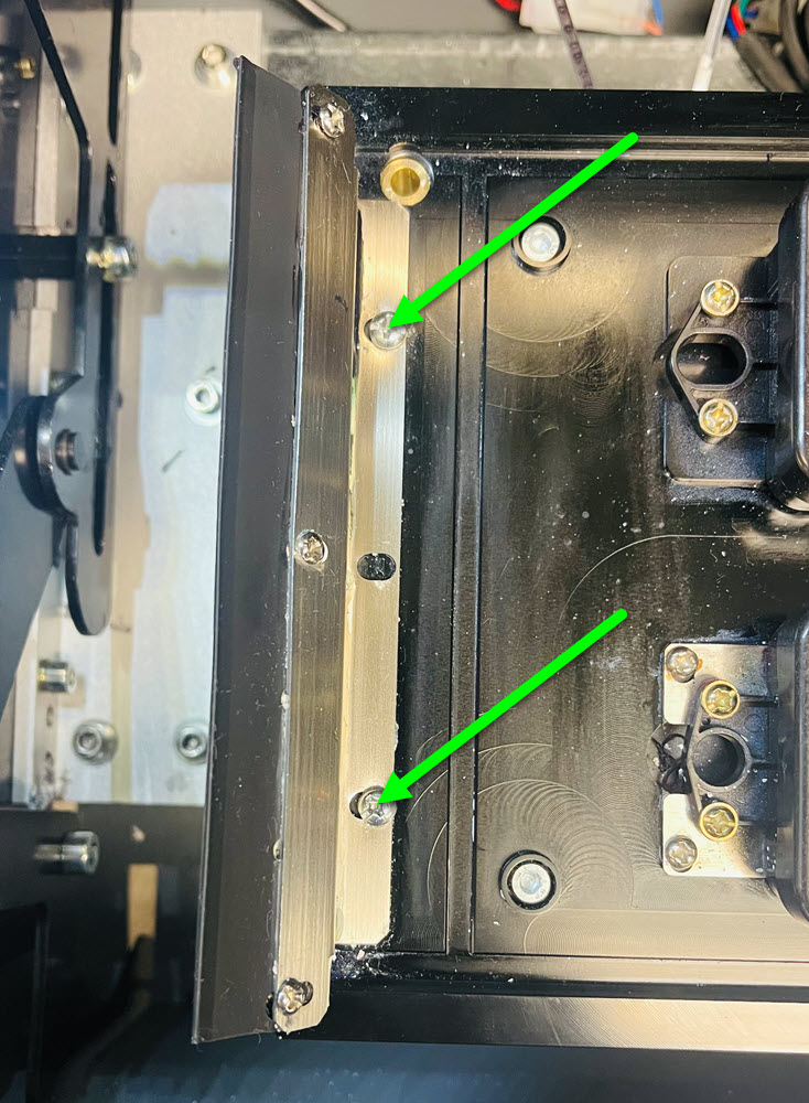
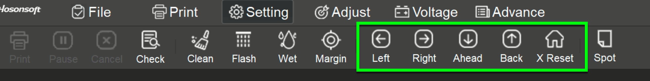
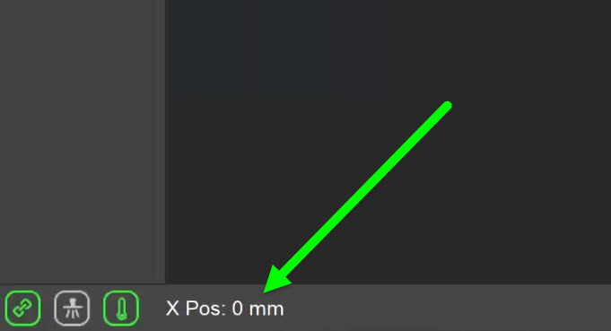
When the head is parked on top of the capping station, the X Position should be 0. When the head is moved all the way to the left, it can vary but should be around 1020. Move the head into the center of the printing deck and look at the X Position in the bottom left corner of PrintExp.
Since the X Position is not between 0 and 1020, then there may be an issue with the encoder sensor or connection. If the encoder cable is not tucked under the head board, it could hit the frame while printing. Power off the printer and then back on to reset the carriage position over the capping station. Once the heads are capped, power off the printer. After checking the connection and cable, power back on.
Remove the top panel on the printer.
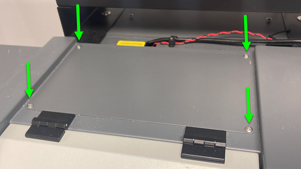
Check this connection and make sure the cable is not extended out on the back side.
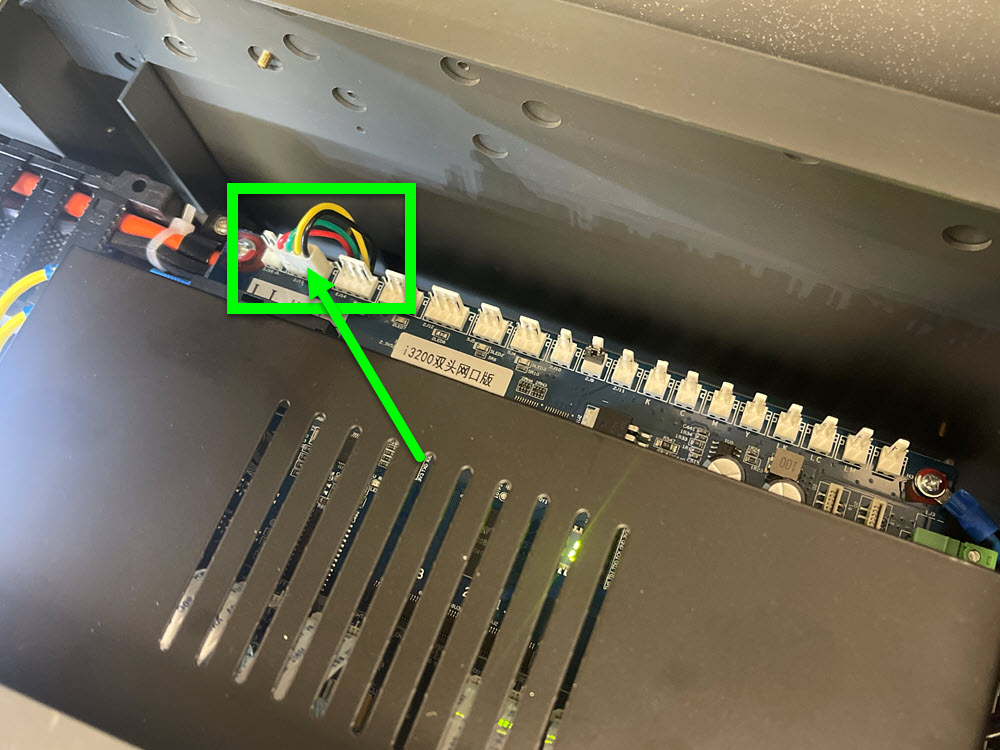
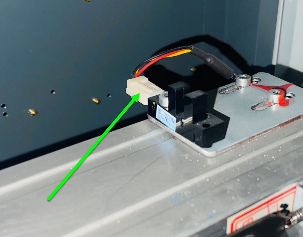
Since the head did not move to the right, check the homing sensor located on the inside top right of the printer.
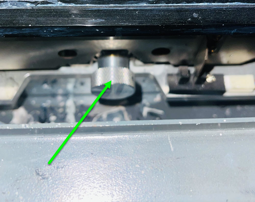
Power off the printer, lower the capping station by rotating the silver knob counter-clockwise all the way, move and align the heads over the cap tops and raise the capping station by rotating the knob clockwise until the cap tops push up against the print heads.
The sensor needs replaced. Your printer will have come with a spare sensor in the printer kit. If you do not have this sensor, if it is under warranty or you need to purchase this sensor, please open a ticket.
Power off the printer with the head in the center of the printing deck. Power the printer back on.
If the capping station homing sensor is not functioning, the station movement will go up and grind since it cannot drop down into the homing sensor. Check the connection of the sensor. This can be found in the bottom right corner of the capping station which can also be accessed from the right door panel.
The capping station sensor needs replaced. Your printer will have come with a spare sensor in the printer kit. If you do not have this sensor, if it is under warranty or you need to purchase this sensor, please open a ticket.
Everything appears to be functioning as it should. If this is still an issue, open a ticket with your test results.
If the head cannot move to the right but can move to the left, it's possible the sensor on the capping station is not functioning. Check the connection of the sensor, it's located in the bottom right of the capping station. You can also access this by opening the right panel door..
The X Positive Max Distance needs adjusted. The video demonstrates the DTF24H4 which has a max distance of 1160. The DTF24H2 has a max distance of 1020. If 1020 proves to be too wide after adjusting the gear ratio, reduce the number to 1015. Follow the video for further instructions.
Power off the printer and rotate the capping station dial counter-clockwise all the way. Push the head carriage to the left and into the center of the printing deck and power on the printer.
If a transfer feels oily or as it sits, oil drops are formed, this is typically from undercuring, even if the transfer has the texture of an orange peel. Increase the Oven Controller temperature by 5 degrees at a time and test.
If the film sits for too long without any movement or the oven controller temperature is too high, the film can become burnt or scorched. Due to various environmental conditions, we advocate the temperature to be set to 125C.
If the film starts and stops quickly, then each area of film will be exposed to direct heat for a longer period of time. When the belt stops, wait for the belt to start moving and time how long it takes for the belt to stop again. We try to have the belt moving for at least 45 seconds. If it is starting and stopping much quicker than that, decrease the belt speed to time up with the printer's film advancement. Rotate the belt speed knob into the minus position for 1/2 a second and let go. You should be able to observe the belt slowing down and a series of beeps. Continue to do this until the belt pauses for a minimum of 45 seconds before it begins moving again.
If this does not resolve the issue, then reduce the temperature on the oven controller by 5 degrees and test. Be sure to not go too low or you may not get a properly cured transfer, leading to poor pressing and/or oily prints.
A fume extraction system is great to remove odors, smoke and help regulate and even out the internal temperature of the oven. When the settings are not dialed in properly for the dryer, there can be unwanted results.
If the airflow is set too high, additional heat can be pulled out and the temperature probe will be effected by being "cooled" off. One of the evidences of this is whatever your set temperature is, the system may not be able to keep up with that temperature. If this is the scenario, then the lamps turn on hotter, even though the reading may not reflect that. This can cause scorching, burning of the film and excessive smoke.
If the system is set too low, smoke may not be removed from the system and your prints may not be evenly cured, giving you a gritty and uneven texture on your transfer.
Turning the dial all the way to the right on the extractor, lowers the aiflow while to the right increases. Adjust the airflow to correct the issue you may be experiencing. For additional airflow connected but not the fume extractor, we recommend a unit that can produce a minimum of 240CFM with a variable speed controller in order to adjust as needed.
Try increasing the temperature on your dryer by 5 degrees at a time. If this does not resolve the issue. it is recommended to add either a fume extraction system or some type of inline exhaust or fan.
A fume extraction system is great to remove odors, smoke and help regulate and even out the internal temperature of the oven. When the settings are not dialed in properly for the dryer, there can be unwanted results.
If the airflow is set too high, additional heat can be pulled out and the temperature probe will be effected by being "cooled" off. One of the evidences of this is whatever your set temperature is, the system may not be able to keep up with that temperature. If this is the scenario, then the lamps turn on hotter, even though the reading may not reflect that. This can cause scorching, burning of the film and excessive smoke.
If the system is set too low, smoke may not be removed from the system and your prints may not be evenly cured, giving you a gritty and uneven texture on your transfer.
If you are researching inline exhaust fans, we recommend a unit that can produce a minimum of 240CFM with a variable speed controller in order to adjust as needed.
A fume extraction system is great to remove odors, smoke and help regulate and even out the internal temperature of the oven. When the settings are not dialed in properly for the dryer, there can be unwanted results.
If the airflow is set too high, additional heat can be pulled out and the temperature probe will be effected by being "cooled" off. One of the evidences of this is whatever your set temperature is, the system may not be able to keep up with that temperature. If this is the scenario, then the lamps turn on hotter, even though the reading may not reflect that. This can cause scorching, burning of the film and excessive smoke.
If the system is set too low, smoke may not be removed from the system and your prints may not be evenly cured, giving you a gritty and uneven texture on your transfer.
Turning the dial all the way to the right on the extractor, lowers the aiflow while to the right increases. Adjust the airflow to correct the issue you may be experiencing.
While the printer is powered on, physically push the head carriage left or right.
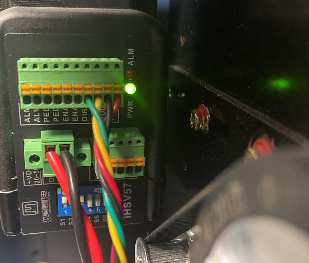
Open the left door of the printer and check for a green light on the motor
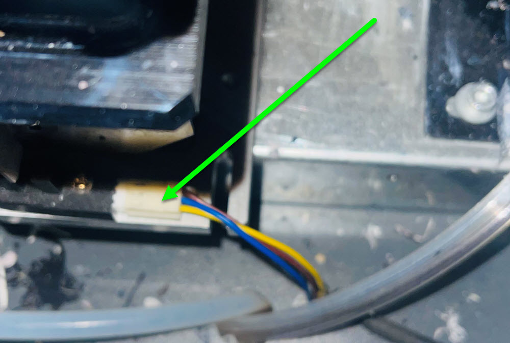
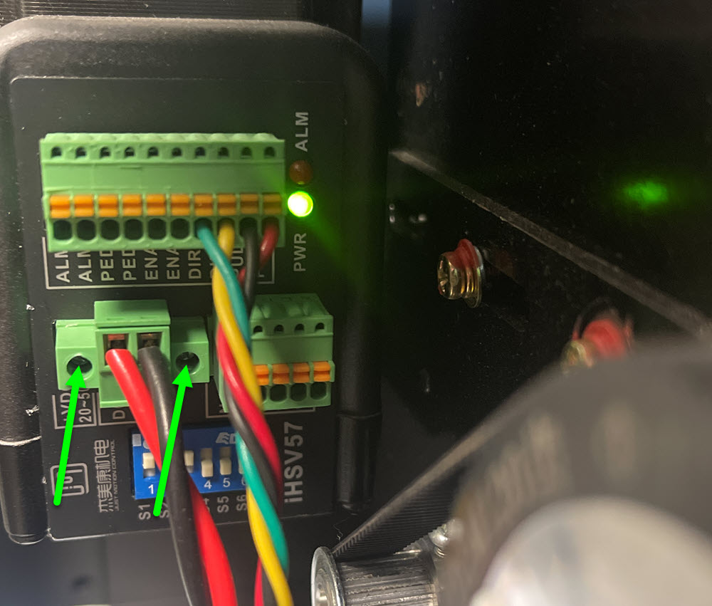
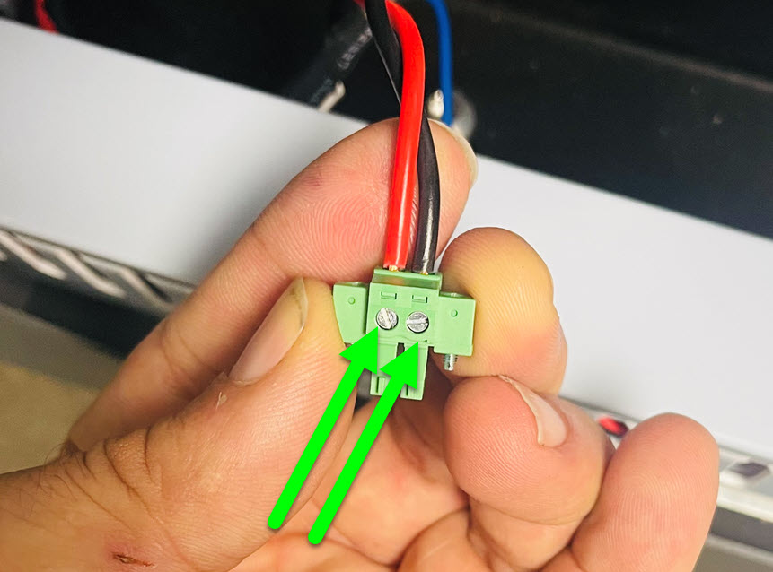
Power off the printer and check the power cable coming into the carriage motor by loosening the side screws, pulling out the connector, tightening the wires and pressing back into the motor firmly. Power back on and test.
It is possible there is either a power supply or motor issue. Please open a ticket for further assistance.
Power off the printer and check the multi colored wiring coming into the carriage motor in the left door by pulling out the connector and gently pulling on each colored wire. You may be able to push a pin or small paperclip into the yellow button. While pressing the button, pull the cable out and then reinsert it and let go of the button, the cable should be secure. Plug the connector back into the motor, power on and test.
Count the amount of times the motor blinks before it pauses and begins the blinking cycle again. Open a ticket with your results.
If the head moves to the inkstack and it is capped, the printer is functioning properly. If it is not, open a ticket for further assistance.
If the issue is related to the media take up roller not functioning, try using the switch in one direction and then the other.
If the issue is related to the film pulling too aggressively, loosen the adjustment knob and hold on to the roll, at the correct tension, you can hold the roll and the motor will still move. It only needs to be slightly loose in order to pull the film against the roll.
If the motor is not functioning or this was not related to your issue, open a ticket for further assistance.
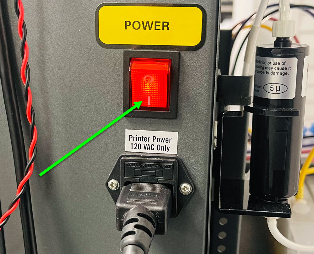
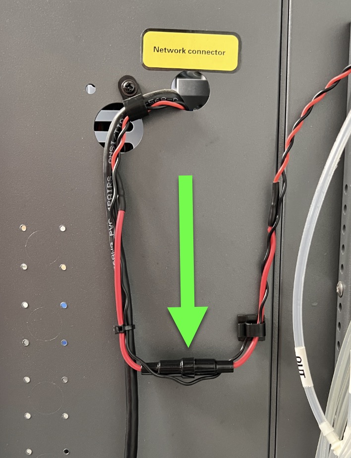
With the breaker in the down position, is there a red light on the white power strip. Also test to see if the breaker stays in the up position.
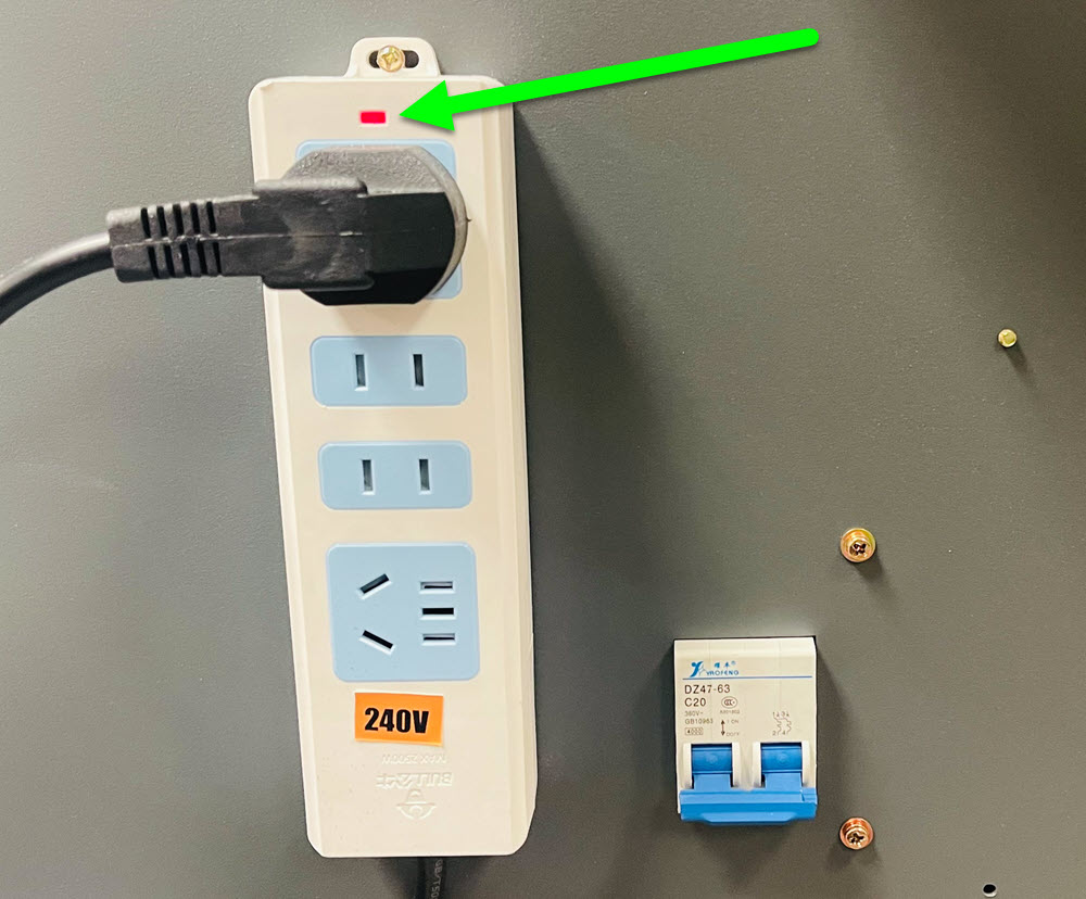
The power coming into the dryer from your outlet is directly connected to the breaker and the power strip. This allows the power strip to be on at all times, even if the dryer is not powered on. If the red light on the power strip is not on, there is no power coming into the dryer. Check the breaker panel in your building that is supplying the power to the dryer. If you are unsure if you are getting power, consult with an electrician. You can open a ticket to address the issue, but without a red light, we cannot confirm you have power coming into the dryer.
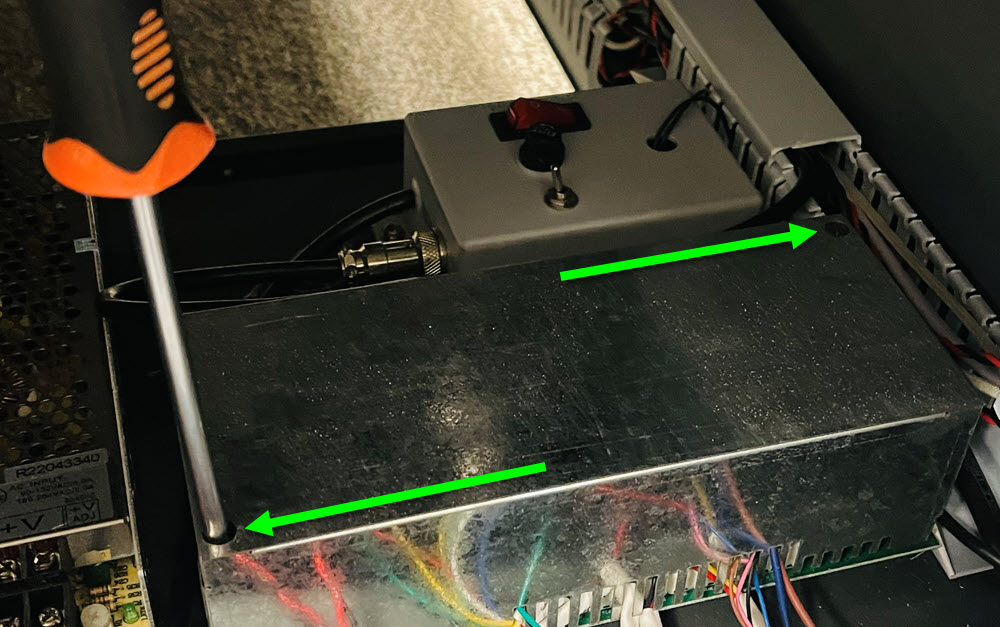
It's possible the power supply is not functioning. Remove the back panel of the dryer by loosening each of the screws, then sliding the panel up and out. If the fans are in the way, you can either remove them or work around them.
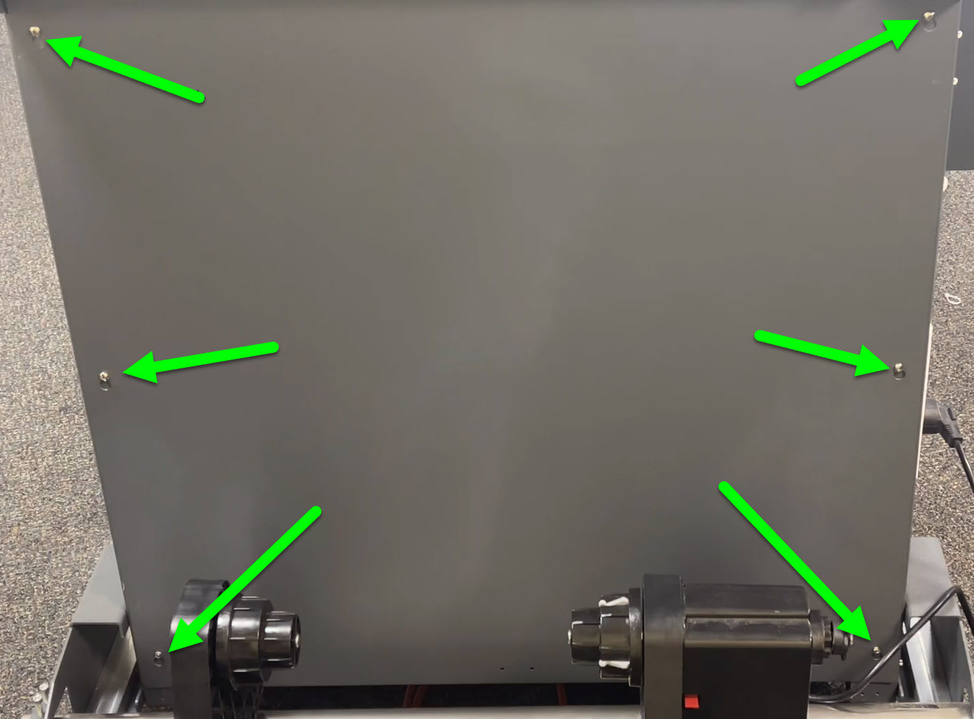
Follow the video and open a ticket for further assistance. If you are not comfortable testing electrical components, consult with an electrician.
Since you are getting power to the dryer, open a ticket with a description of the issue(s).
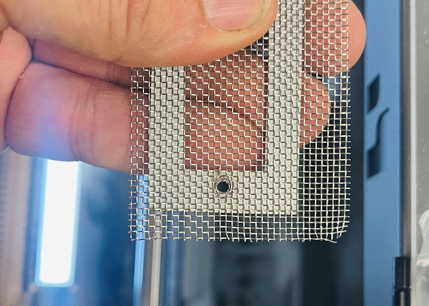
The adhesive (TPU) powder is hygroscopic in nature, which means it will draw moisture from the air. This will thicken the powder and potentially cause issues for it to pass through the screen. The dryer uses a 20 mesh screen but we also provide a 30 mesh screen with your purchase, which would have come in the standard kit. To avoid dropping screws into the powder, place some scrap film in the bottom of the unit.
Click on the Image to Enlarge in a New Window
Remove the 8 screws on the long side of the mesh opening.
Remove the remaining 2 screws while reaching inside the bottom of the chamber to catch the mesh and frame.
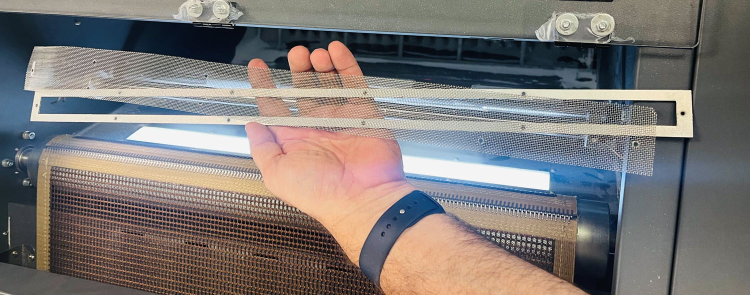
Line up the new mesh and frame at the outer hole, place one screw in the outer end of the powder hopper and begin screwing the mesh and frame in place but do not fully tighten. Stretch to the opposite side and repeat the process. Attach the 8 remaining screws around the perimeter and once all screws have been started into the frame, fully tighten them.
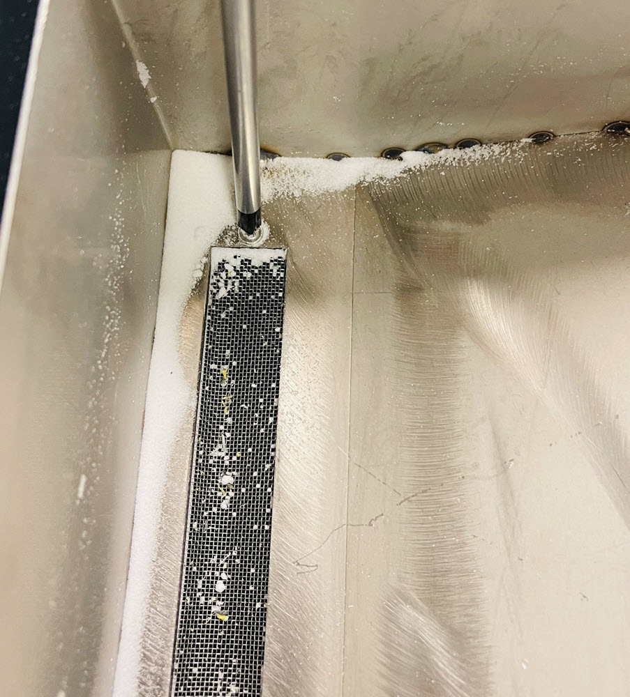
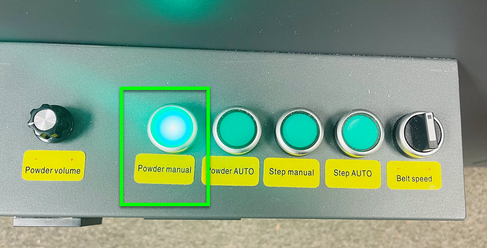
With the manual powder button turned on, pull on the inside wall of the powder hopper until all powder has dropped. Pulling on the side wall should create more of a vibration to allow the powder to flow.
Confirm there is no debris in the powder and continue using.
The hopper can be repositioned for a better vibration. Loosen the four screws that hold the hopper in place and move the hopper towards the printer and tighten the screws while the manual powder is on. If successful, the vibration should be louder and cause more powder to drop. If this does not resolve the issue and the powder has too much moisture, it may need to be replaced. If none of these resolve the issue, open a ticket for further assistance.
Click on the Image to Enlarge in a New Window
Turn off the manual powder button and open the back panel of the dryer.
Flip the silver switch on the powder control box in the opposite direction and turn on the manual powder button. One of the directions should vibrate more than the other.
Click on the Image to Enlarge in a New Window
Power off the system, remove the black Fuse holder in the powder controller box and replace the fuse with a 250v 5amp Fast or Quick Blow fuse. If this did not resolve the issue, open a ticket for further assistance.
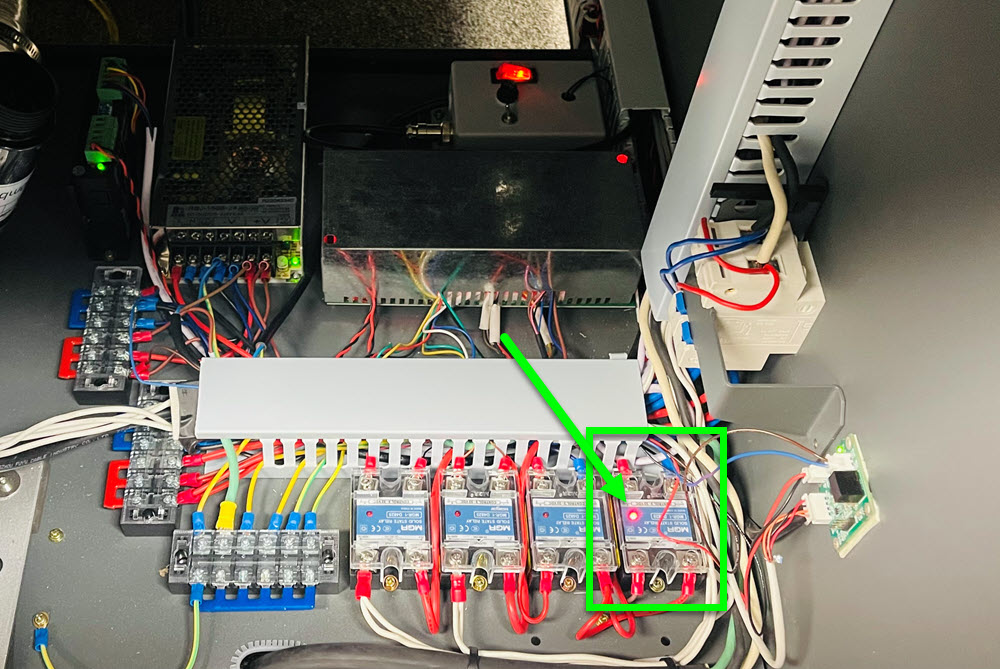
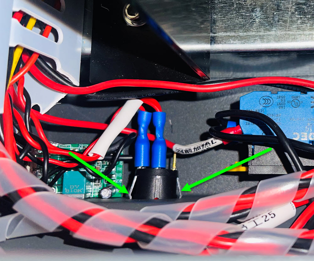
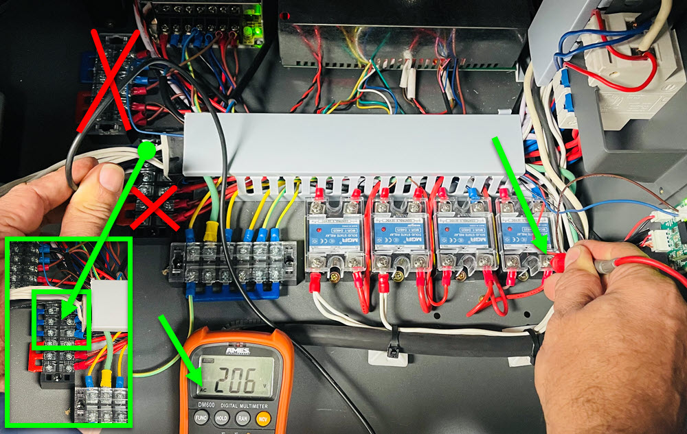
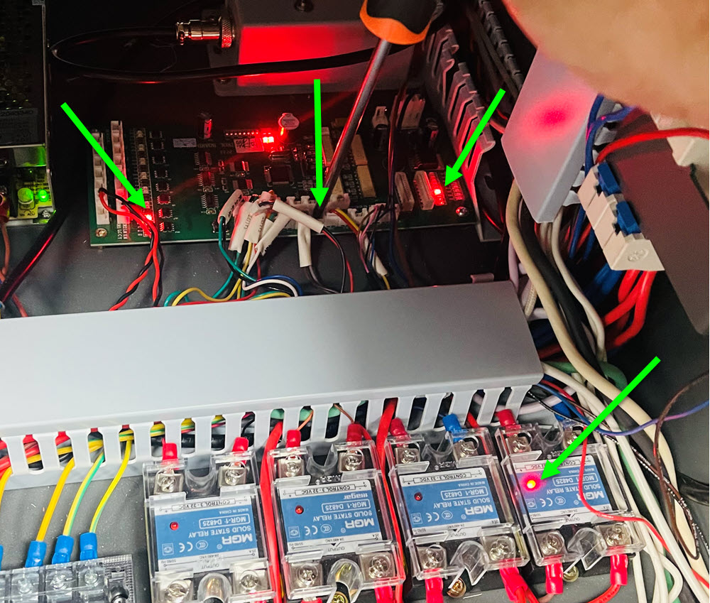
Using a multi-meter, change your setting to AC current which will have the symbol of a V with a wavy line above it, if your meter has both in one, change the function to AC. With the manual powder button turned off, touch the red lead on your meter, to the red wire in the bottom right of the relay and the black lead on your meter to one of the blue terminals as shown in the photo, you should get 208 - 240 volts, depending on your service. This confirms you have correct power coming into the relay.
Click on the Image to Enlarge in a New Window
Now place the red lead on the bottom left red wire on the same relay and the black lead on one of the blue terminals above, with the manual power button turned on, you should have 208 - 240 volts. This confirms you have correct power coming out of the relay.
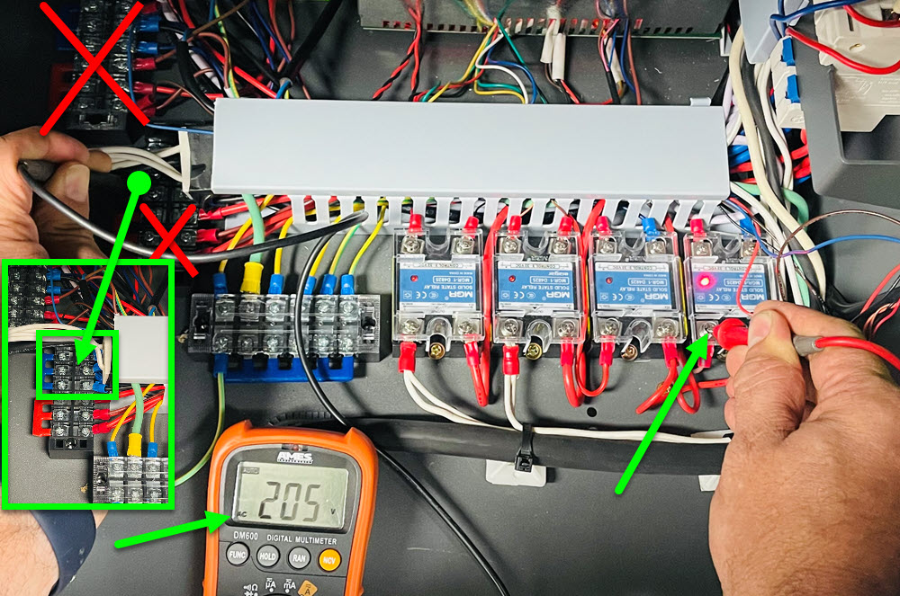
If you have correct power coming in but not coming out, the relay needs replaced. Open a ticket for further assistance.
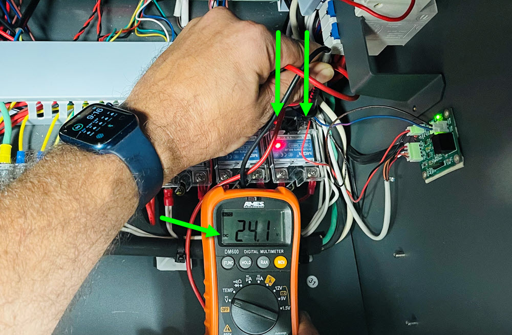
With the powder manual button turned on, test the DC power coming into the relay for around 24v. Match the red wire with the red wire on the DC input of the relay and the black wire with the black wire. If you do not have 24v coming in, it could be a button issue, if you do have 24v coming in but the light is not on, the relay may need replaced. Open a ticket for further assistance.
Click on the Image to Enlarge in a New Window
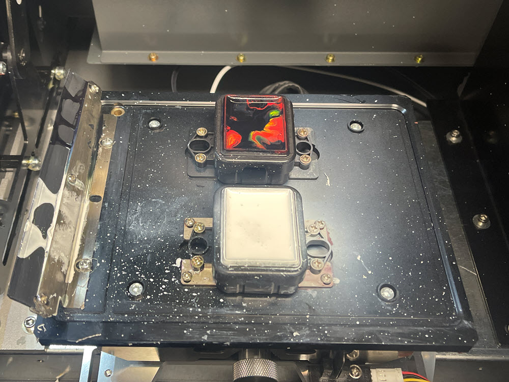
Since the ink system is gravity fed, if the printheads have too much or too little pressure on them, even with a perfect nozzle test and registration, there could be banding. If there is too much pressure, ink can bead up on the bottom of the print head channels, if there is too little pressure, ink can retract into the printhead nozzles when printing heavy colors. In addition, environmental conditions can influence this, so in order to correct it, the ink cartridges have the ability to raise and lower the amount of ink in the system, creating more or less pressure as needed. Once this is set properly, there shouldn't be a need to change it. It is typical for the cartridge to be 1/4 - 1/3 full. More can be added, but rarely would the cartridge ever require it to be more than half full.
When banding occurs, the first test would be to move the head all the way to the left and look at the channels on the surface of the head. If there is a build up of ink within the channel, it is possible the ink in the cartridge is too high, causing more pressure. If there is no ink buildup on the channel, then it's possible the ink may be too low and "starving" the head of ink. The image represents an area where you might see a line of ink build up or drips.
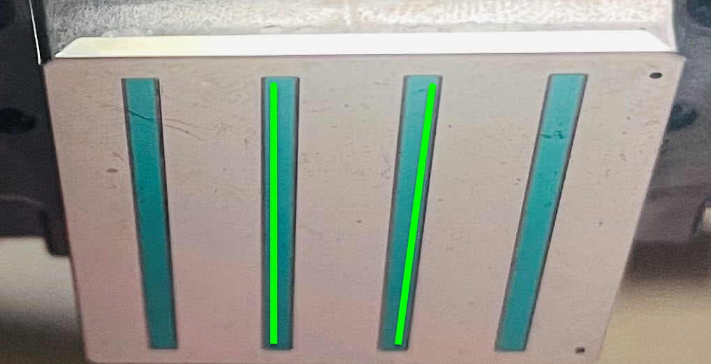
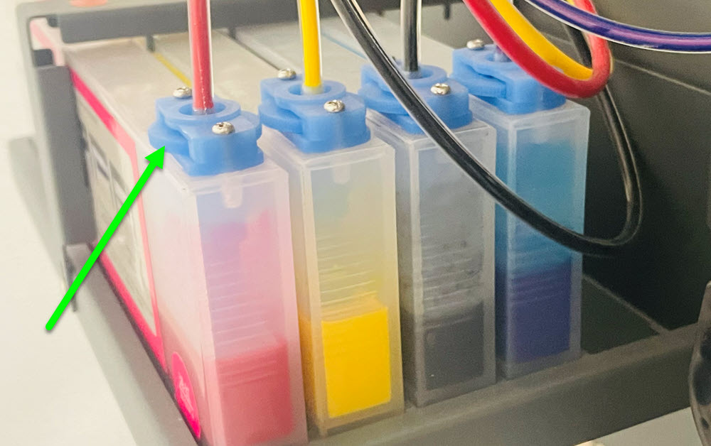
Inside of the cartridge is a float, rotating the blue dial clockwise will raise the float, allowing more ink in. Rotating counter-clockwise will lower the float and allow less ink in. When lowering, the ink will need to be used to see a difference. As it lowers in the cartridge and gets to the float level, it will begin letting ink back into the cartridge, so you won't notice immediately. It would be recommended to turn the dial 2 full rotations and test. Rotate in whichever direction as needed.
Since the ink system is gravity fed, if the printheads have too much or too little pressure on them, even with a perfect nozzle test and registration, there could be banding. If there is too much pressure, ink can bead up on the bottom of the print head channels and block the nozzles. If there is too little pressure, ink can retract into the printhead nozzles when printing heavy colors. In addition, environmental conditions can influence this, so in order to correct it, the ink cartridges have the ability to raise and lower the amount of ink in the system, creating more or less pressure as needed. Once this is set properly, there shouldn't be a need to change it. It is typical for the cartridge to be 1/4 - 1/3 full. More can be added, but rarely would the cartridge ever require it to be more than half full.
When banding occurs, the first test would be to move the head all the way to the left and look at the channels on the surface of the head. If there is a build up of ink within the channel, it is possible the ink in the cartridge is too high, causing more pressure. If there is no ink buildup on the channel, then it's possible the ink may be too low and "starving" the head of ink. The image represents an area where you might see a line of ink build up or drips.
Inside of the cartridge is a float, rotating the blue dial clockwise will raise the float, allowing more ink in. Rotating counter-clockwise will lower the float and allow less ink in. When lowering, the ink will need to be used to see a difference. As it lowers in the cartridge and gets to the float level, it will begin letting ink back into the cartridge, so you won't notice immediately. It would be recommended to turn the dial 2 full rotations and test. Rotate in whichever direction as needed.
If the head moves to the left and doesn't stop, it's possible the homing sensor is not functioning. Check the connection of the sensor on the inside top right of the printer.
Open a ticket for further assistance.
It is possible there is a motor issue. Please open a ticket for further assistance.
Power off the dryer and remove the rear panel.
Using a screwdriver (preferably with a magnetic tip), insert into the two holes on the cover to remove it from the dryer control board. If either of the two screws have been dropped, be sure to locate and remove them before powering on the dryer.
Remove the powder manual button connection from the control board, power the dryer back on and push a screwdriver into the socket. The light on the left and right of the board and the relay should turn on, as well as the vibrating motors. If this is the case, the button itself or the connection to the button may be bad. Open a ticket with the results of your test.
Click on the Image to Enlarge in a New Window
If you need a better visual for which cable to disconnect: Click Here to Download the Oven Controller Board Connections The correct connection is marked 7 on the diagram.
When installing the control board cover, if you find it difficult to screw it back in place, the cover can sit over top of the control board and cables and does not need to be screwed in place.
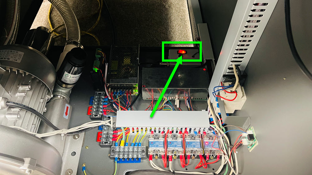
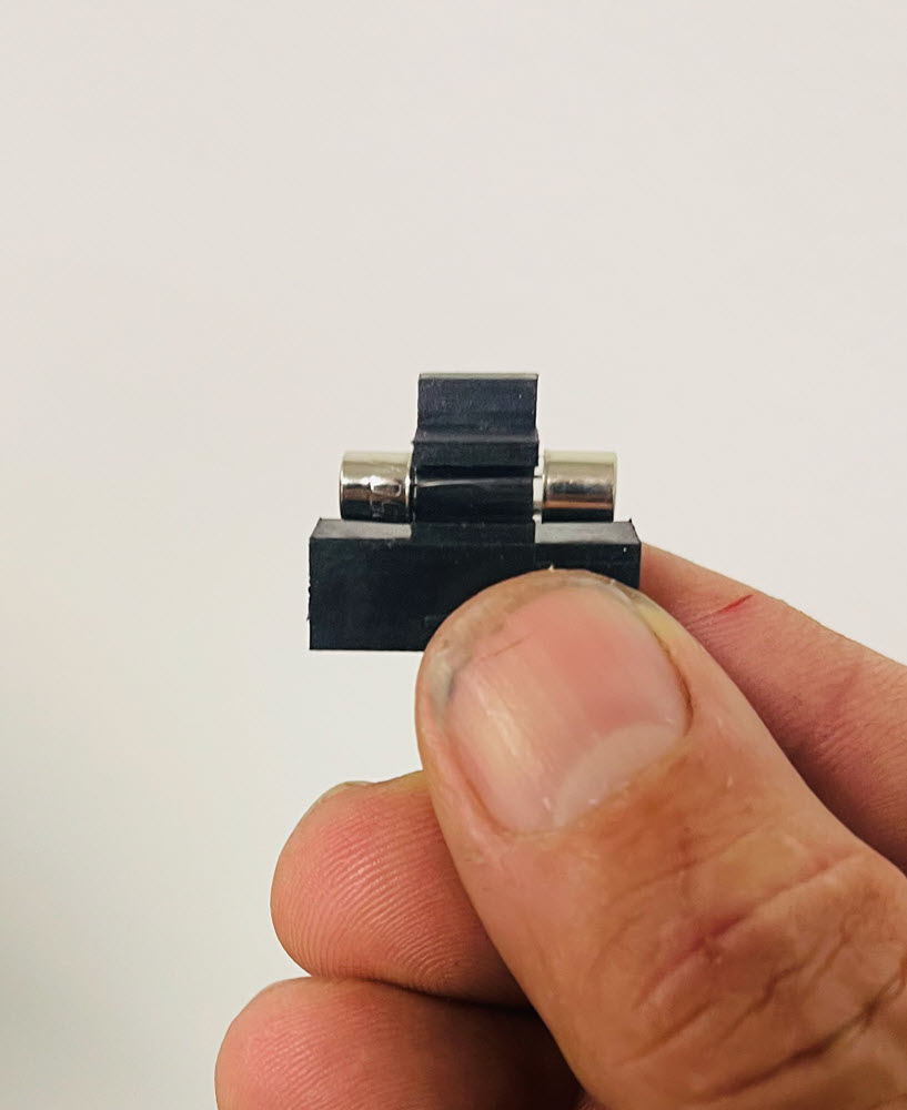
Power off the printer, remove the power cable and pry open the bottom tab of the fuse holder. Test to see if the fuse is blown. If it is, replace it with a 15Amp 250v fast or quick blow fuse.
Since this did not resolve the issue, it is possible it is either a connection to the switch or it is the switch itself. Open a ticket for further assistance.
Since the switch is in the one position and lit up red, it's possible the power supplies may be causing the issue. Open up the back panel on the left side of the printer.
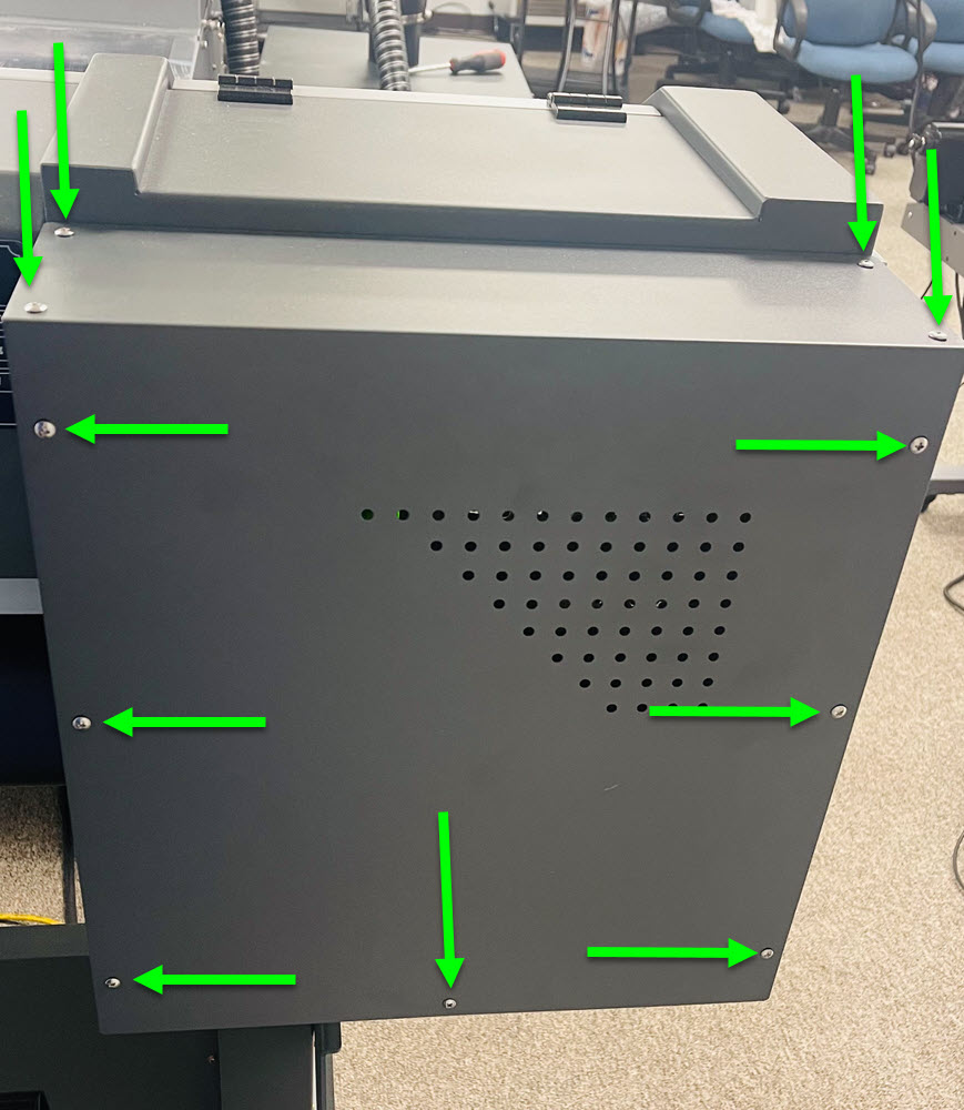
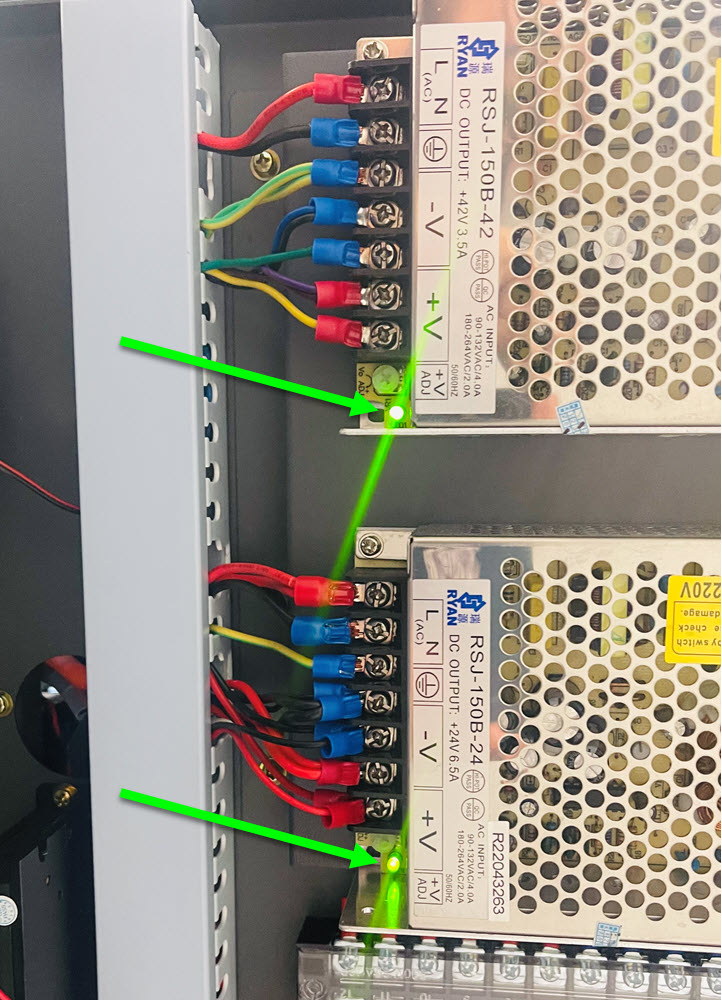
Each of the 2 power supplies should have a green light on them. If they do not or the light is dim, it's possible the power supply itself is bad or a component attached to it could be bringing the supply down. Open a ticket for further assistance.
The interior LEDs of the printer and the vacuum fan on the printing deck share the same button. When the switch is in the 1 position, what is the result?
Click on the Image to Enlarge in a New Window
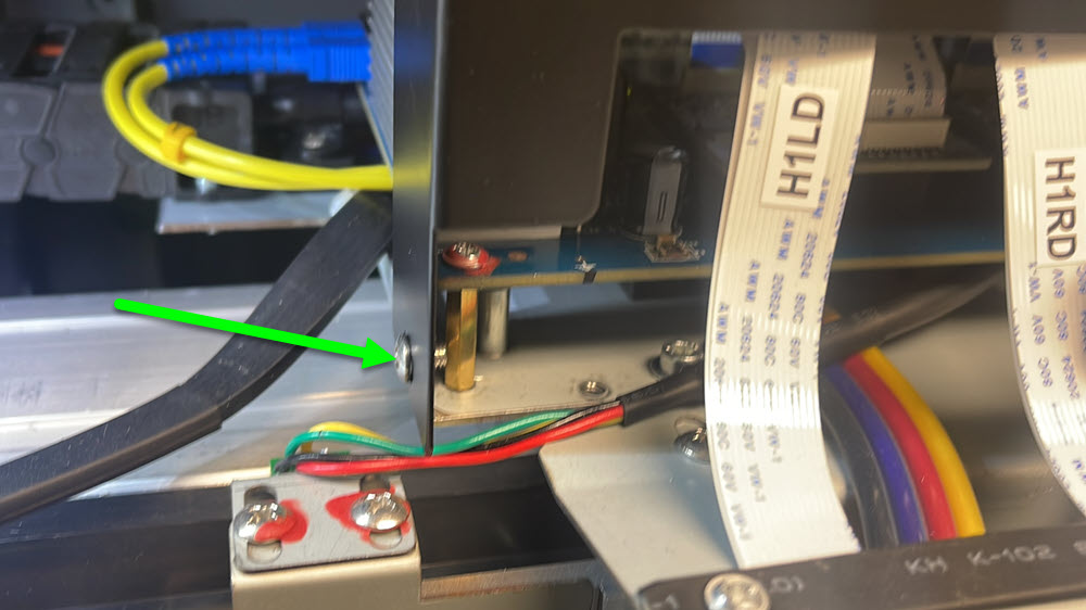
Disconnect the wire in the 0 position of the switch. Using a multi-meter, set it to read DC current and test the red wire for 24V DC power. The black lead can touch a screw on the printer as shown in the photo. The resulting voltage can be anywhere close to 24V but does not need to be exact. If the voltage is 0 or extremely low, choose "Voltage" is 0V as your selection below.
Click on the Image to Enlarge in a New Window
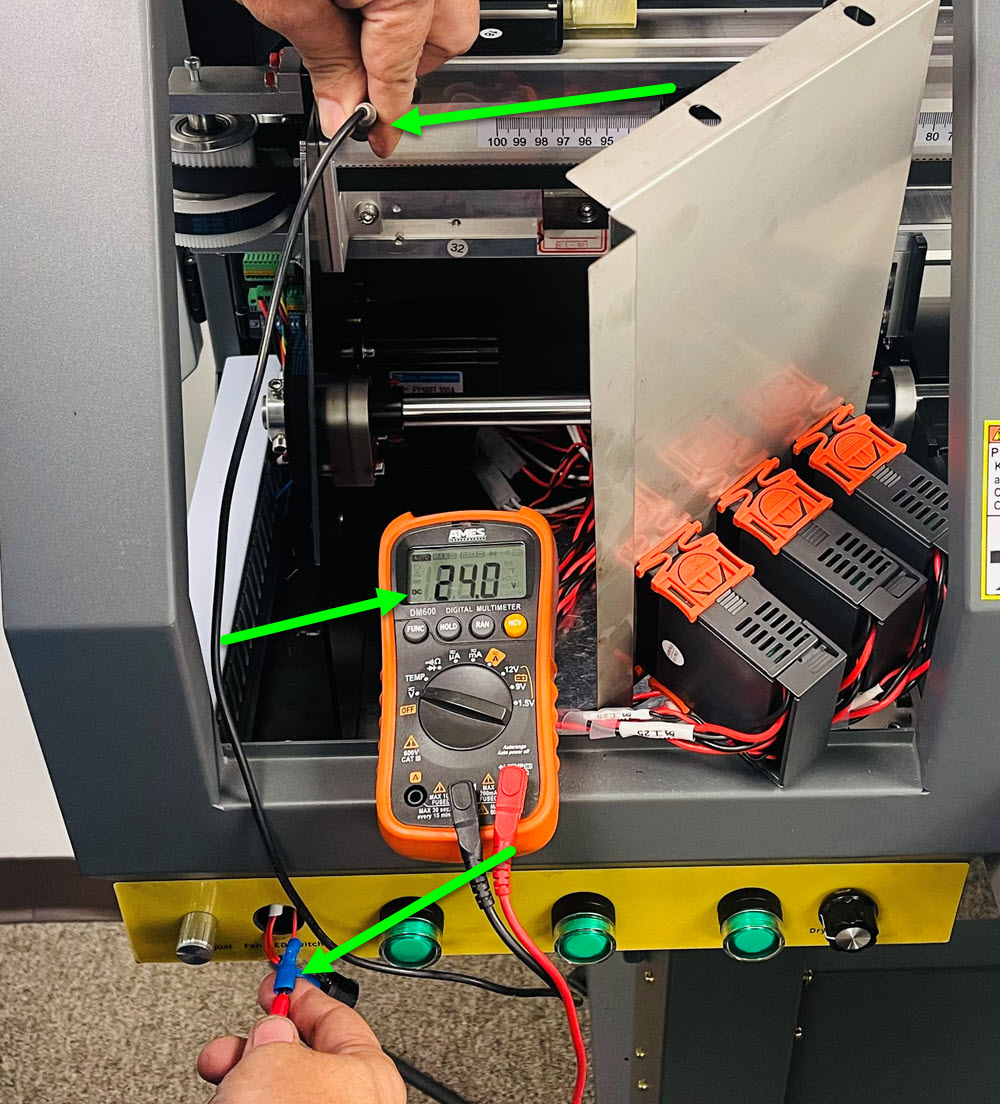
If the voltage is 0V or much less than 24V, there could be an issue with your power supply or connect from the supply to the switch. Open a ticket for further assistance.
Follow the video to test LED/fan switch. Open a ticket for further assistance.
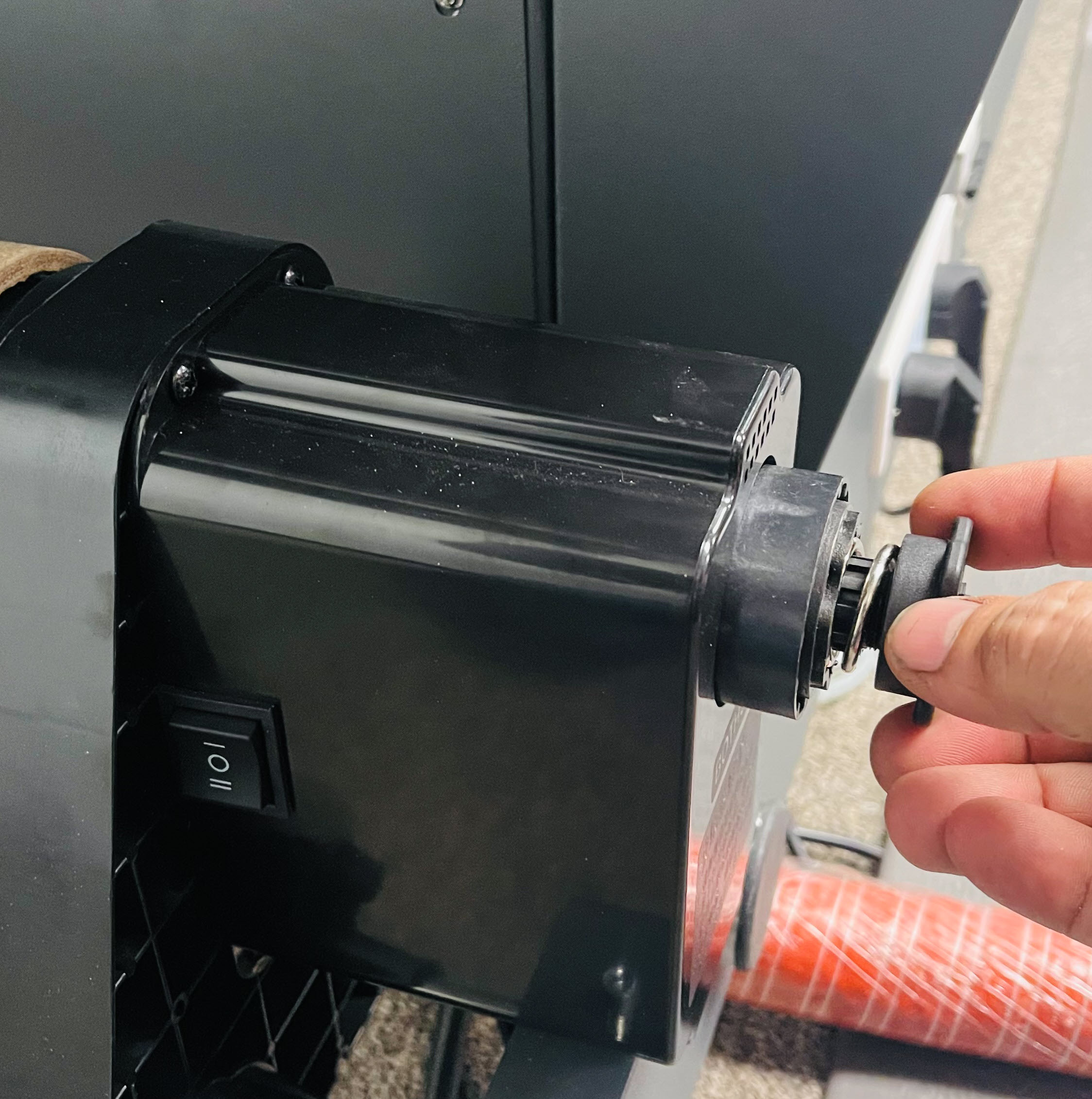
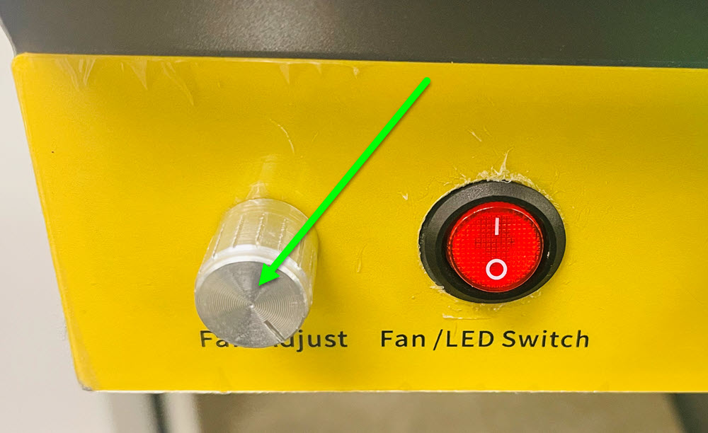
Turn the fan adjust dial all the way to the right.
Click on the Image to Enlarge in a New Window
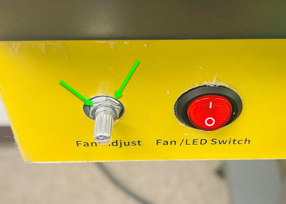
Power off the printer and pull the dial straight out and off of the speed controller, then remove the nut and washer, set aside. Push the speed controller into the printer, open up the left door and bring it up to gain access to it.
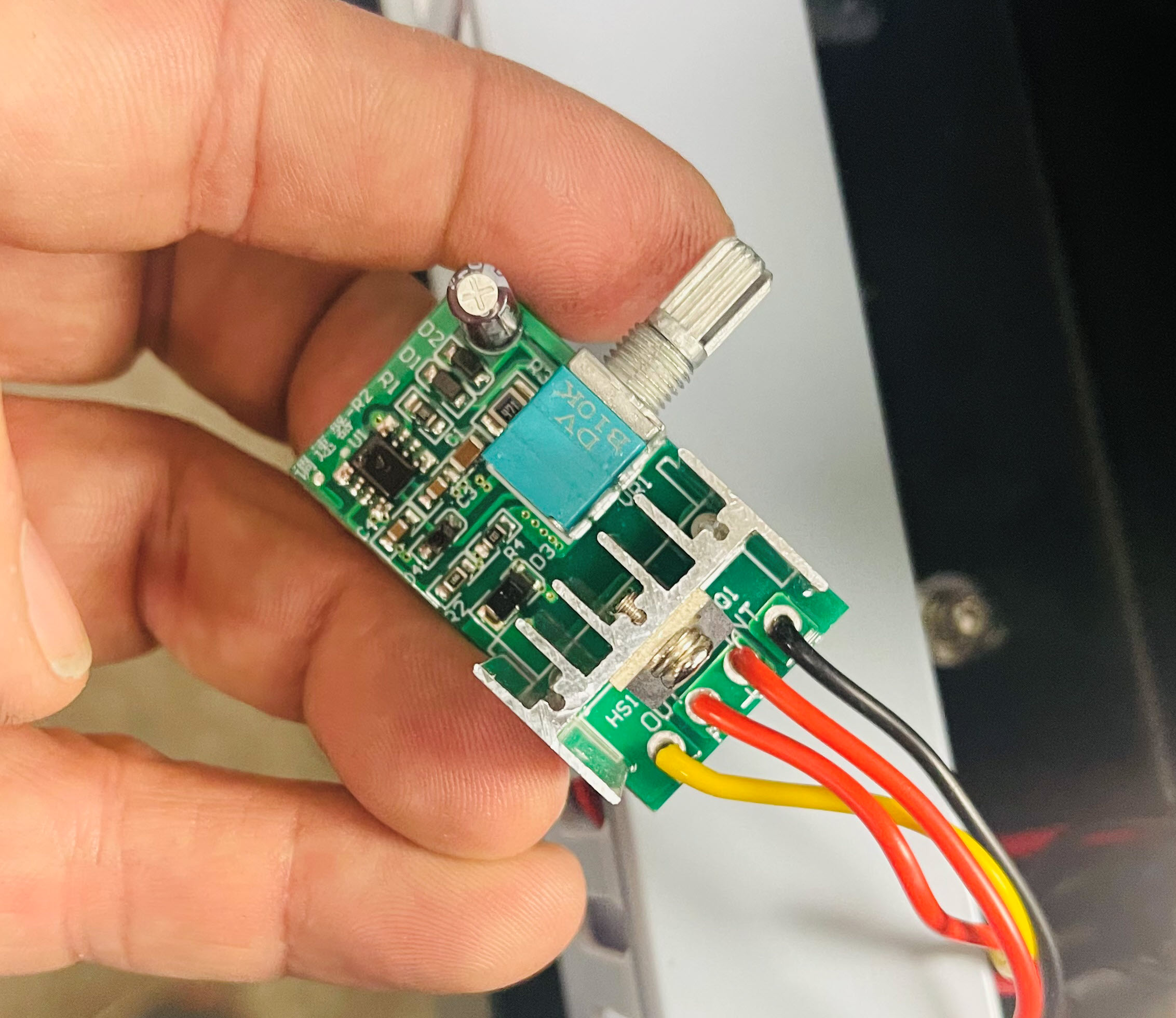
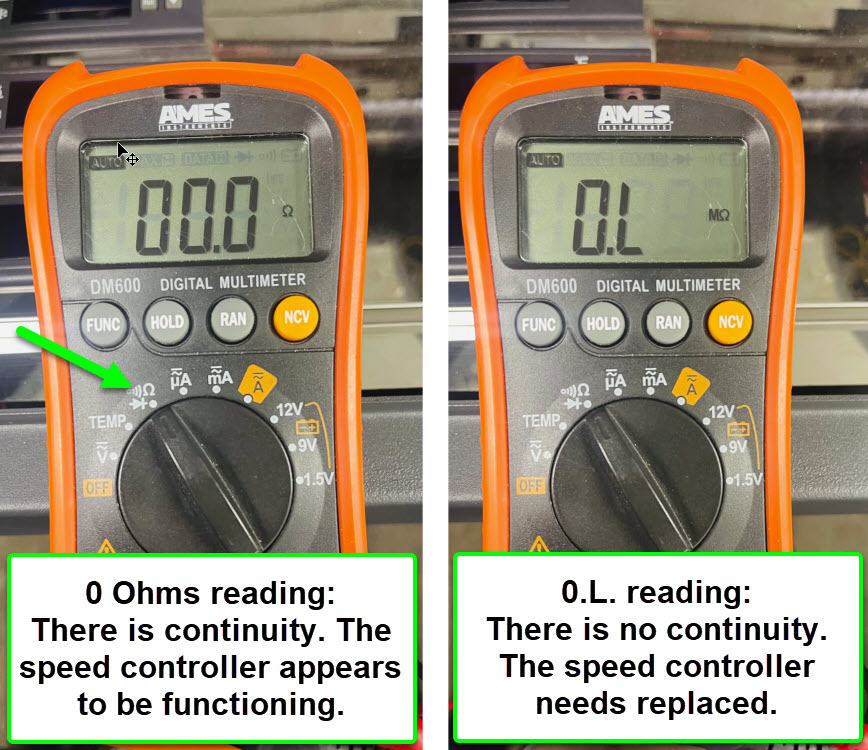
With the dial rotated all the way to the right, turn the speed controller upside down. Using a multimeter set to Ohms, touch the red lead to one of the red wire connections and touch the black lead to the other red wire connection. You may need to press firmly to to ensure a good connection.
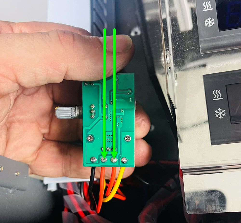
With the multimeter set to Ohms, if the controller is working properly, the reading will be 0. If it is not working properly, it would be 0L. It is possible the reading would be 0 and still not function properly. Open a ticket for further assistance.
Remove the top panel on the printer.
Remove the single screw on the left side of the head cover and the 2 screws on the right side.
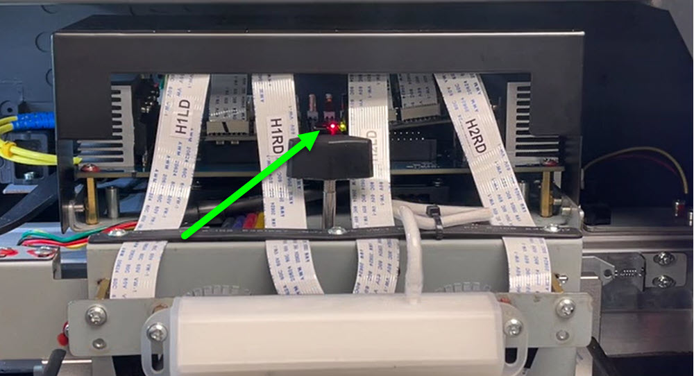
On the top of the carriage is the head board. Is there a red flashing light?
If you are missing 1 or more Print Queues, the simplest way to restore them is to use the Clean feature. Follow the video for detailed instructions.
There are typically two scenarios in which the printer will stop printing mid-way through a print with the printer screen saying "Moisturizing".
1. The computer goes to sleep. In this instance, you would want to change your power settings to not let the computer sleep.
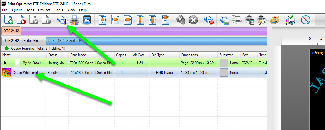
2. When it is printing, another print job is sent to the printer. To avoid this, while the printer is printing, bring in your next jobs into the rip, select them and instead of choosing print, click the Spool icon to the left of the printer icon. This will process the job only and not send it to print. Then when your job is completed, select the job you had processed and then click the print button and it will send the job immediately.
Click on the Image to Enlarge in a New Window
When the printer is in the Paused state like this, it's actually in an error state where the only way to get out of it is to reboot the printer.
When a printhead carriage prints, pauses, prints, pauses, etc., this is almost always in relation to the computer using too much memory. This could be from too many applications open, not enough memory on the computer, heavy network usage, or printing files from a server and not on the local computer.
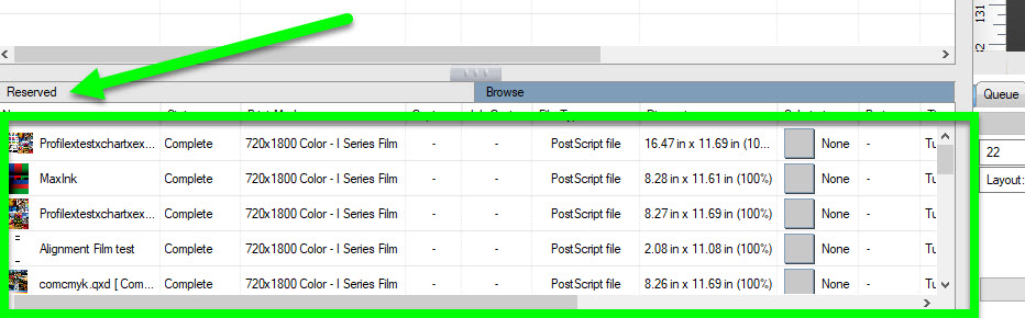
You may also want to clear out the Job Reserve in Print Optmizer. To do this, select the jobs in the bottom left window of program and press the Delete key to remove them. Too many files in this area of Print Optmizer will require more processing power, which slows the printer down and can slow the program itself down.
Click on the Image to Enlarge in a New Window